
Recently a friend of mine asked me to repair his Power Amplifier for him.
I very reluctantly accepted his request because the amplifier weigh almost 90 kg.
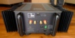
Its really a heavy monster. The amplifier is a very expensive piece of Hifi designed and made from Denmark and is called the Gryphon Reference one Power Amplifier.
It is a pure class A power amplifier able to deliver some 150 Watts (rms) of pure listening pleasure. My friend said previous repair engineer gave up on repairing it. He said when power up the main fuse will blow. I thought it would be a piece of cake, output transistors or the capacitors, right?

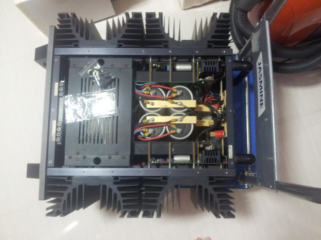
The amplifier basically is constructed of 2 identical channels, consisting of the main power transformation and rectification stage, a dedicated smoothing and regulated power supply for the VA stage each, the T-shaped circuit VA stage circuit board and the emitter follower Power output stage. So there are 2 massive toroidal transformers (I think is 1400 VA) with 4 large main capacitors (47,000uF each 63vdc 105 degC). The toroidal transformer is resin sealed to prevent vibration/hum so it will not be repairable.
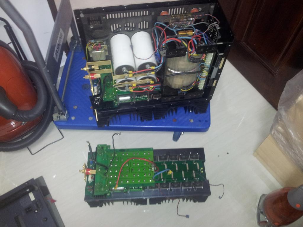
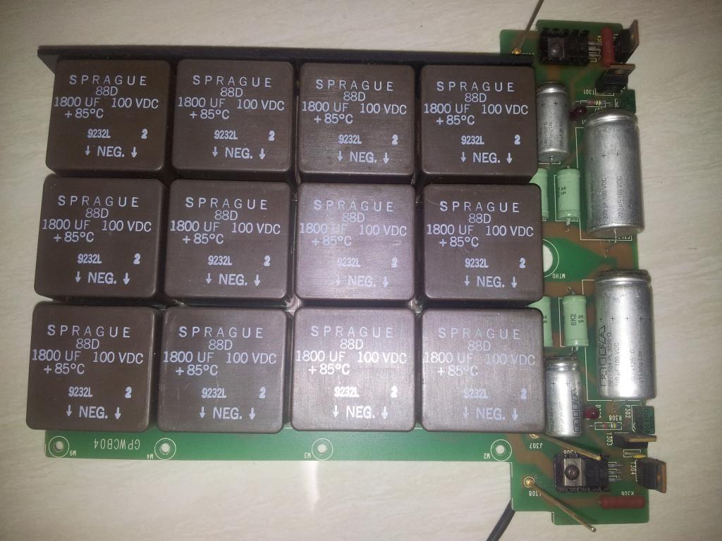
The dedicated smoothing and regulated power supply is very special because it consist of square shape capacitors that I have not seen before. It is the spraque 88D, 1800uF 100vdc 85 deg.C square shape capacitors, configured in a matrix of 3 X 4. I don't think we can find any direct replacement if any of these need to be changed. However, as I have read, spraque capacitors are known to be built to last, some 50 years.

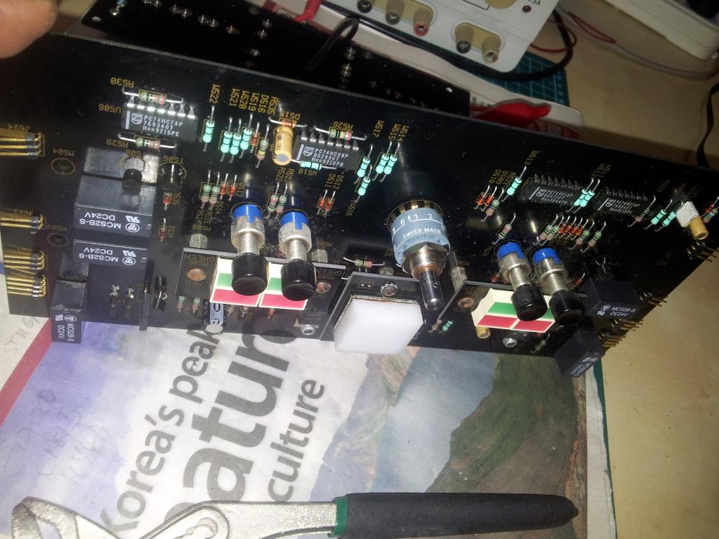
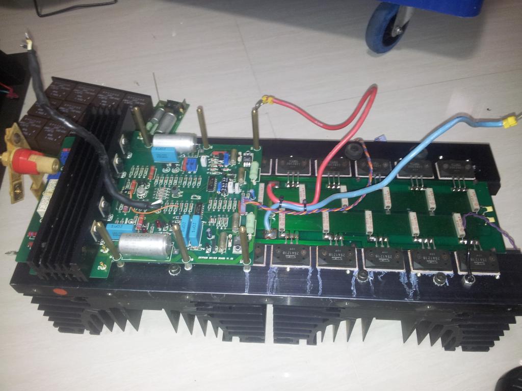
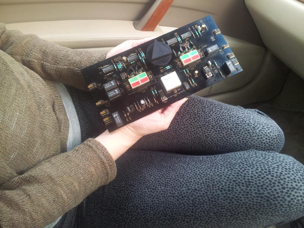
After removing the above mentioned regulated power board, we can see the T-shaped VA stage which also contained the protection circuitry inside. I think the heart and soul and most of the design dollars of the amplifier is in this VA stage. The protection circuitry includes in the form of integrated circuits, If DC or HF is detected at the input, a monitor will cause the unit to mute. Another circuit monitoring the difference between input and output will blow internal control board fuses by a darlington pair transistor, while the temperature sensor (NTC 10K) circuit which is not in the VA stage but housed in the control board, will temporarily cut power supply to the amplifier section until the temperature recovers. The VA stage is all of direct coupled design eliminating the use of capacitor couplings (which distort and soil the purity actually). I must not forget to tell you that the input is of balanced XLR design and any unbalanced signal source will likely activate the protection circuitry. This board also contain the 3 bias adjusting trimmer resistor, which provides idle, 75% and 100% bias. At 100% bias and no input, the power supply current from a 230 AC main is about 4.3A, which is about 700 watts RMS of zero work wasted Power. Only the HiFi Purist can justify that energy equation.

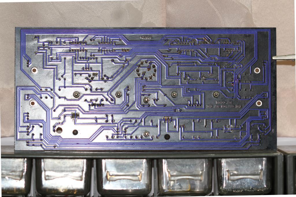
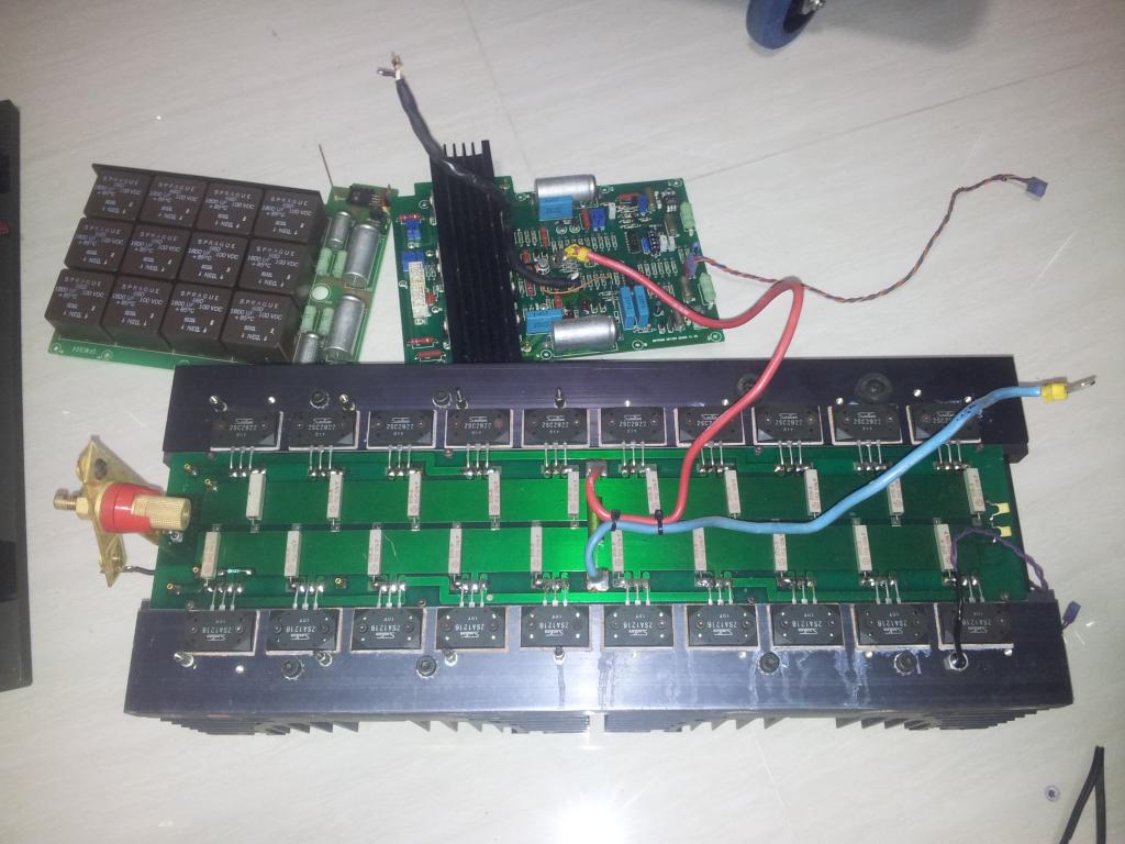
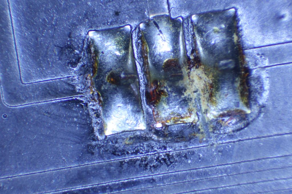
The Power Stage is basically 10 pairs of Sanken (2SC2922 and 2SA1216) complementary transistor pairs mounted sturdily on a very large heatsink. I think the heatsink is proprietary made. If there is going to be a problem of blown fuse, its going to be in this section. A measure of the output reviewed that this stage is shorted. The only way to check for transistor short in this stage is unfortunately very tedious to desolder at least 2 of its legs for measurement, as the emitter followers are all paralleled together. All the transistors are tested with a transistor tester and reviewed in good condition. So where are the shorts? Surprisingly, the short was a solder short at the narrow center section of the tiny pad (where the 2 regenerative resistor meets). I think it was a poor soldering work from manufacturing some 20 years ago lurking for disaster. The short was removed and a simple measurement now reviewed megger ohms range. :-)

Some final notes. The amplifier uses very high grade components even for trivial control circuit like precision 1% 6 color band resistors, elma selector switch 2 poles X 6 ways which is about US$80 a piece because its gold plated, chiefly for medical grade, even though it just control small DC currents. Also, poor manufacturing because the circuit board don't appears to be washed off the soldering flux. And also be very careful of back injury because this amplifier is deadly heavy.
thanks guys for reading this, this is my first posting in Elektro Tanya. Hope you like it.


Hello! Very impressive description of great repair work, with good photo's. Thanks for your effort in sharing with us.
Greetings.
0
Hello !
Really good work !
Congratulation !
Best regards lm
0
Hello,
I say thank you for having shared your experience with us. Good work and heavy (in the real meaning)!
BR.
0
Hi,welcome on board!
It was very interesting topic,write more about your repair adventures!
(You had luck with this amp,it was easy to repair)
Is it seriously 90 kg?
Best regards,
torokj
0
Hi Armadillo-welcome in our group,
Its really nice work-tnx!
Question; can you upload please your SM, than we dont have some Gryphon material...
Thanks a lot, all the best!
Kari
0
Hi,
nice, very nice.
Best regards
0