
Hello,
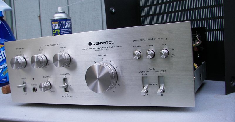
Last week I picked up a nice Kenwood KA-3500 40watt intergrated amplifier in pretty good shape.
Upon using it a bit more, I noticed a bit of distortion at high volume, more so in the left channel. I checked the DC offset at the speaker terminals, and the L channel said 100 mV, while the R was 25 mV. I understand this isn't so good for the L channel at least, but unfortunately this amp doesn't have any DC offset adjustments. Am I right in saying that to fix this I'd have to replace the output transistors?
--
On a related issue, in the service manual I found the section on BIAS adjustment, and I read online how it can affect the DC offset. So I hooked up my voltmeter to the test points, and I got 4 mV on the L, and 8 mV on the R. In the manual it says should be 40 mV.....(!). Is there something wrong here? I tried carefully adjusting them, but they only go to 30mV with the pots fully on, this doesn't seem right to me.
--
I compromised at 20 mV BIAS for both channels, and now the DC offset is 50 mV for L, and 5 mV for R, which is better, less than half what they were. I'm wondering, will I damage anything doing this, should I put them back to where they were?
--
The service manual is on site here.
Let me know if you want me to upload an english copy of the Owner's Manual, it has a better schematic in it all on one page, easier to read.
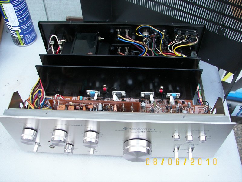
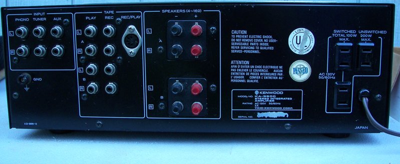
I've also included some pictures. They're not my actual unit, but mine is exactly the same, but less dusty.
--
Thanks for reading this. Many thanks in advance, and have a peaceful Palm Sunday! :taps2:
Bellarmine
Hi Bellarmine!
I came across your posting because I was researching this amplifier a little bit (thinking of maybe buying one from someone).
Here is the thing. The quiescent current/voltage adjustment on the output devices influences the DC offset (as you have seen empirically for yourself), but we don't want to be setting the DC offset by manipulating the bias. That is not the purpose of bias! The purpose of bias is to set up the amplifier in order to minimize crossover distortion. If you are interested in this topic more, please look up a good book, such as Audio Power Amplifier Design Handbook by Douglas Self.
You don't want to be compromising bias for the sake of reducing offset.
A 100 mV offset is not particularly serious. Into an 8 ohm resistive load, that is only 1.25 mW dissipation. I think you should reduce it though, just for the exercise of doing it!
The amplifier is DC coupled, so that a small offset voltage at the inputs of the differential stage of the power amplifier will result in an output offset. Where does the input voltage comes from? It comes from the base currents that are coming from the differential input transistors. In the schematic that is available on this site, these are Qe1 and Qe3 in the power amplifier section (for the left channel). When the base currents from Qe1 and Qe3 encounter a resistance on the way to ground, that resistance develops a voltage, of course, and that voltage appears at the bases, creating offsets.
The way the amplifier design deals with this is by having identical DC resistances facing both bases. This is what the 56K resistors are all about: Re5 and Re13. These resistors are identical on purpose: to create the same voltage so that the there is no net offset. They do different jobs, though! The 56K resistor on Qe1 is shunt to ground, and basically determines the input impedance of the stage. On Qe3, the 56K resistor is the upper resistor of the voltage feedback line. The lower resistor is the 3.3 k Re11. But that resistor is coupled to ground via a capacitor, so it doesn't matter from a DC viewpoint. The only DC resistance faced by the base is the 56k resistor, which is connected all the way to the output of the amp. (The amp output is a low impedance to ground, being a voltage source).
Anyway, so a possible reason why that channel has so much offset is that the resistor values may have drifted. Or were not accurately matched to begin with: note that according to the BOM (bill of materials parts list), these resistors are carbon units with 5% tolerance!
It may also be that the capacitors in the respective cicuits are leaky. If the 47uF Ce7 is leaking, then it will spoil the offset. On the other side of the diff amp, a leaky input coupler (Ce1, 47 uF) will also create a similar problem: it will let some current get around the 56k resistor, thereby shifting the voltage. Electrolytic capacitors from the mid 1970's: think about it!
If you really wanted to be obsessive about getting it to zero, you could replace the input side 56k Re5 with, say, a 47k resistor in series with a 20K potentiometer (wired as a rheostat).
Anyway, I hope that these clues prove fruitful in your quest to null the offset of the Kenwood! Good luck.
0