
Hi everybody,
I have Philips 40PFL7007K/12 on repair. TV does not start up. I have checked the PSU and it seams to be OK. There seam to be problem on the main board.
What I have tried…
Well, there is +3V3-STANDBY coming from PSU to main board. This feeds up the main processor. This voltage has also been used to switch TV on. I have checked that switching signal from POWER ON button goes back to main board. But I did not check this whole path towards the processor as it is BGA package and it is covered by ceramic cooling plate.
And here comes what is not clear to me.
1. How to check if the main processor works? Does it work on the +3V3-STANDBY when TV is is standby mode?
2. Can I somehow check if the PSU is working? May be by activating some pin?
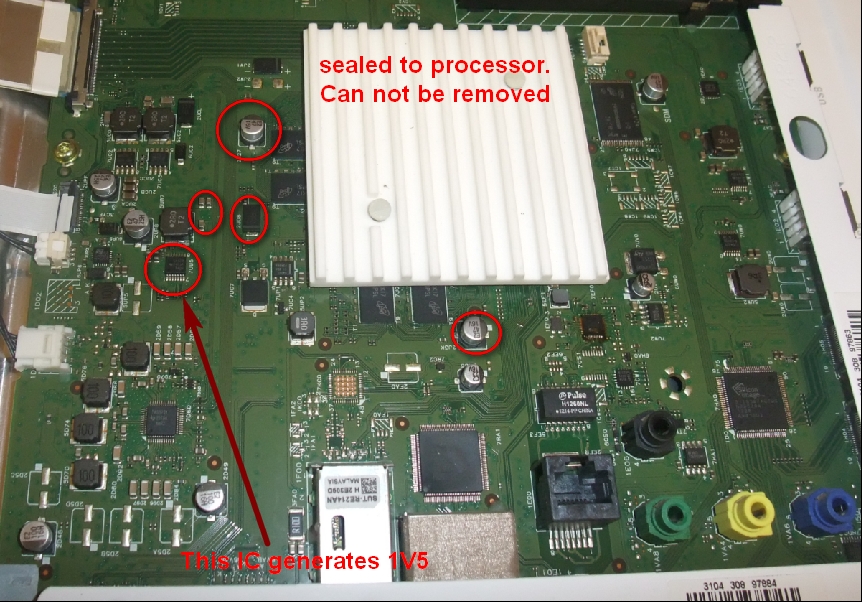
3. I have noticed by measuring (ohm-meter) some capacitors on the main board (in circles on the picture) that there is very low resistance on them (4.5ohms). In the scheme it is shown that these capacitors are on the 1V5 (1.5V) line. Is this OK? Basically it does not give much current as I = 1V5 / 4R5 = 333mAmps. What do you think? Certainly there are low voltage data parts (RAM. Processor …) connected and such resistivity might be correct….?....
What I have also find that this 1V5 is split into 1V5M0 and 1V5M1. See the picture. I have removed the coils and measured resistance. Then 1V5M0 shows about 15ohms and 1V5M1 shows about 6,5ohms.
The service manual is on this link:
http://elektrotanya.com/philips_ch.qfu1.1e_la.pdf/download.html
Thanks Martin
THe BGA processor is bad!!!
0
Hello Martin!
The 1'5V line you can measuring very low inpedance is correct! (This parts working very high frequency therefore all elements are low inpedance).
Your problem is basicly the BGA processor defect. First time try to repair this section. Take off the mainboard and go to special techniker who has BGA rework station and try to reflowing the processor. Very inportant: this board thinkly then average board and the processor reflow curve are different. Useing slow heat up and lower soldering temperature. All Philps tv sets 90% are BGA soldering problem.
Good luck!
Old Philips engineer!
Laszlo
0
Hello again,
Thank you very much for your help But I didn't mention that the STBY LED (red) blinks twice repeatedly.
Is it also the BGA chip or maybe it can be a corrupted eeprom file?
Thank you in advance.
0
Hello!
When the stby led blinking twice that mean on the SSB one or more subpower supply is bad. First time I controll all output of subpower supply. If any output has low inpedance (lower than 2-3 ohm) there are the problem. Basicly some smd parts are wrong, 100nF or processor is bad.
László
0
Hi dear member,
I read your topic on ElectroTanya website about your problem with your Philips TV.
I have the same problem with my own TV.
I also measured the resistance across the 1V5 and it saw very low impedance 4.5Ω.
Did you repaired your TV?
Do you have any tips for me?
I do like the picture on this TV and I really want to keep it.
Thank you very much for your help and time.
Regards
0
Hi,
it is very possible there is no problem with a mainboard. Much often the problem is with LED background invertor. The driver IC sends to MCU a power good signal immidietly. If the invertor have any problem, there is no way to power up tv set. The main suspect is transformer. If you have datasheet from LED driver IC you can finde a way to override this protection. I have same problem. I measured transformer secondary with any possible means, after blocking protection invertor starts to work but only then was clear the secondary is faulty when starts to sparkling between windings.
Best regards
0
Hi bluemoon,
To be honest, I am a newbie in TV repairs. First I thought I can find all you are writing about but I have found that I could not.
There is no much information about T-CON board in the manual.
I suppose the T-CON board is under the cover on the bottom of TV. Just shown on the picture. Here is where the transformer is sitting?
I do not much understand what parts you mean by LED driver IC (one on the T-CON?). And where to localise information about power?
Thanks Martin
0
Hi,
you mised the target. Tcon is probably Ok, LED driver is faulty, i think. I marked it with green sqare. On the flip side is driver IC. Find datasheet for IC and let me know witch type it is. According the picture i assume the LED invertor is maybe under the hood. If you get power on the connector, marked with green arrow, then you faced with much bigger problem.
Best regards
0
On the flip side there are two ICs.
I suppose you are talking about the gigger one.
This IC is SSC9522S.
The second smaller is the FAN7930C. See the picture.
When I measure the voltage coming from this PCB I see only 3V3. There is not any 12V and so on
Thanks Martin
0
Hi,
the FAN IC is for this 3V3 stby voltage and this is OK. other ic, SSC must be switched on by 1M95(CN4) pin2 (STB). When you switch on the set on this pin must be Hi to ignite the SSC IC. If there is no any change then is the mainboard faulty and maybe is te soft in eeprom damaged as the colegue mentioned in 25c10 SPI.
Best regards
0
STB (pin 2) is 3.1V. I guess this is OK. Then I measured POK (pin 14) and it is actually 0.2V. I am going to check with scheme. Scheme for SSB is in the manual. Martin
0
Hi bluemoon, thanks for your valuable info. I would not have realized that. I am gonna check it.
Thanks! Martin
0
Hi Martin,
Did you measured please desoldered capacitors for such Ohms or faily "only" in-circuit with an Ohmmeter?
You must measure an ESR on that, in best case as desoldered ones...
Kari
0
Hi Kari, yes I desoldered them and measured with ohm meter and esr meter. They look OK. I have desoldered only accesible capacitors. According to the scheme on 1V5 is much more of them. I did not checked them all yet.
Thanks. Martin
0
The flash firmware can also be faulty 25L10
Or Probe RC 5 remote control philips.
0