Service manuals, schematics, eproms for electrical technicians
02.E2P

Type:  (HEX)
(HEX)
(HEX)Size
5.0 KB
5.0 KB
Page
---
---
Category
MONITOR
EPROM
MONITOR
EPROM
If you get stuck in repairing a defective appliance download this repair information for help. See below.
Good luck to the repair!
Please do not offer the downloaded file for sell only use it for personal usage!
Looking for similar 02.e manual?
Good luck to the repair!
Please do not offer the downloaded file for sell only use it for personal usage!
Looking for similar 02.e manual?
Document preview [1st page]

No preview item for this file.
Possible causes:
- No preview picture generated yet.
- It is not a pdf file.
Advertisements
Download free of charge (10 files / day):

Download processing...
Download processing...
- Also known:
02.E-2P 02.E2P 02 .E
- If you have any question about repairing write your question to the Message board. For this no need registration.
- If the site has helped you and you also want to help others, please Upload a manual, circuit diagram or eeprom that is not yet available on the site.
Have a nice Day! - See related repair forum topics below. May be help you to repair.
Warning!
If you are not familiar with electronics, do not attempt to repair!
You could suffer a fatal electrical shock! Instead, contact your nearest service center!
Note! To open downloaded files you need acrobat reader or similar pdf reader program. In addition,
some files are archived,If you are not familiar with electronics, do not attempt to repair!
You could suffer a fatal electrical shock! Instead, contact your nearest service center!
so you need WinZip or WinRar to open that files. Also some files are djvu so you need djvu viewer to open them.
These free programs can be found on this page: needed progs
If you use opera you have to disable opera turbo function to download file!
If you cannot download this file, try it with CHROME or FIREFOX browser.
Translate this page:
Relevant MONITOR forum topics:
Sziasztok,
Az említett projektor beázott állapotban került hozzám, és nem indul el a tápja. Egy problémát vettem eddig észre rajta, a "fő" táp panelba van beforrasztva egy külön kis NYÁK, amin elszállt egy SMD IC, ezért a típusát sem tudom leolvasni... Valakinek lenne ötlete, hogy mi is lehet az az IC? (SM-ben a kis nyákot én nem találtam meg...)
A tápegység típusa: LC403-4001CC, a kis nyáknak is van száma:LC403-4002BC, a kérdéses alkatrész helye a PC202 pozíció lenne:

 A kis nyák helye a nagyban:
 Előre is köszönök mindenféle segítséget!
Üdv,
Viktor
Előre is köszönök mindenféle segítséget!
Üdv,
Viktor
A kis nyák helye a nagyban:
Előre is köszönök mindenféle segítséget!
Üdv,
ViktorSziasztok!
Került hozzám egy ilyen monitor azzal a gonddal, hogy csak a csatlakozót szakították le. Nos innen a tanyáról letöltöttem a rajzot és bekötöttem a csatlakozót, de valami nem stimmel. (a rajzhoz képest mintha ez más lenne) Jelenség: csatlakoztatva a monitort bekapcsol, mégsincs kép. Ellenőriztem a vezetékeket nem-e szakadt valamelyik, illetve nem kötöttem-e el valamit, de hibát nem találtam. Valaki ismeri ezt a fajta monitort? Honnan lehetnék biztos abban, hogy a bekötés jó, vagy a moncsi sztrájkol?
Köszönettel: Kiss Z.
(képen kábel bekötése a csatlakozón gyári, én a másik végével küzdök)
Nem tudom miért nem jártam sikerrel a csatlakozó bekötésével, de végül tanácsokat követve az eredetileg kialakított helyre, egy aljzat beépítésével minden probléma megoldódott.
Sziasztok!
Van egy monitorom, amiben nem lehet állítani a vízszintes méretet, és a vízszintes pozíciót, a kép szélesebb a kelleténél, egyébként tökéletes a kép. A készülék hibátlan volt, a szekrényt tetején az állásban hibásodott meg. Találkozott már valaki ilyen hibával?
Előre is köszi az ötleteket:
Jácint
Sziasztok!
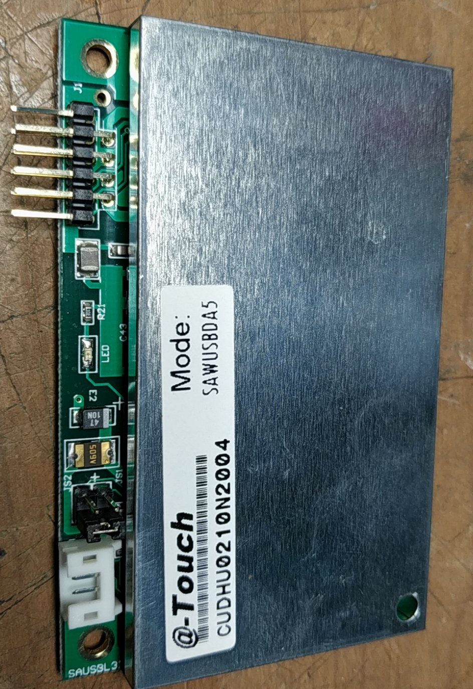 Egy infoterminál érintőképernyő része nem működik, egy 19"os Surface Acoustic Wave elven működő érintőpanel és egy USB-s vezérlő van benne. Hogy lehet eldönteni, hogy a kontroller, vagy az érintőpanel hibásodott meg?
Érintőképernyő típusa: A-Touch SAW19PT1G1
USB kontroller típusa: @-Touch SAWUSBDA5
A drivere, illetve a hozzávaló TouchKit program nem látja az eszközt (0 touchkit devices). Próbáltam egy laptoppal is, az sem látja, ha rádugom az USB-t nem történik semmi, (persze lehet hogy nem is plug and play), hiába telepítem a laptopra is a drivert, az sem látja, ezért nekem a kontroller a gyanús.
Bekapcsolt állapotban a kontrolleren lévő zöld LED folyamatosan világít. USB kábelt ellenőriztem. Az érintőpanel sérülésmentes, a vezetékei nincsenek leszakadva.
Ha valakinek lenne esetleg ilyen működő kontrollere, vagy tud olcsó beszerzési forrást, érdekelne.
Köszönöm!
Egy infoterminál érintőképernyő része nem működik, egy 19"os Surface Acoustic Wave elven működő érintőpanel és egy USB-s vezérlő van benne. Hogy lehet eldönteni, hogy a kontroller, vagy az érintőpanel hibásodott meg?Érintőképernyő típusa: A-Touch SAW19PT1G1
USB kontroller típusa: @-Touch SAWUSBDA5
A drivere, illetve a hozzávaló TouchKit program nem látja az eszközt (0 touchkit devices). Próbáltam egy laptoppal is, az sem látja, ha rádugom az USB-t nem történik semmi, (persze lehet hogy nem is plug and play), hiába telepítem a laptopra is a drivert, az sem látja, ezért nekem a kontroller a gyanús.
Bekapcsolt állapotban a kontrolleren lévő zöld LED folyamatosan világít. USB kábelt ellenőriztem. Az érintőpanel sérülésmentes, a vezetékei nincsenek leszakadva.
Ha valakinek lenne esetleg ilyen működő kontrollere, vagy tud olcsó beszerzési forrást, érdekelne.
Köszönöm!