Service manuals, schematics, eproms for electrical technicians
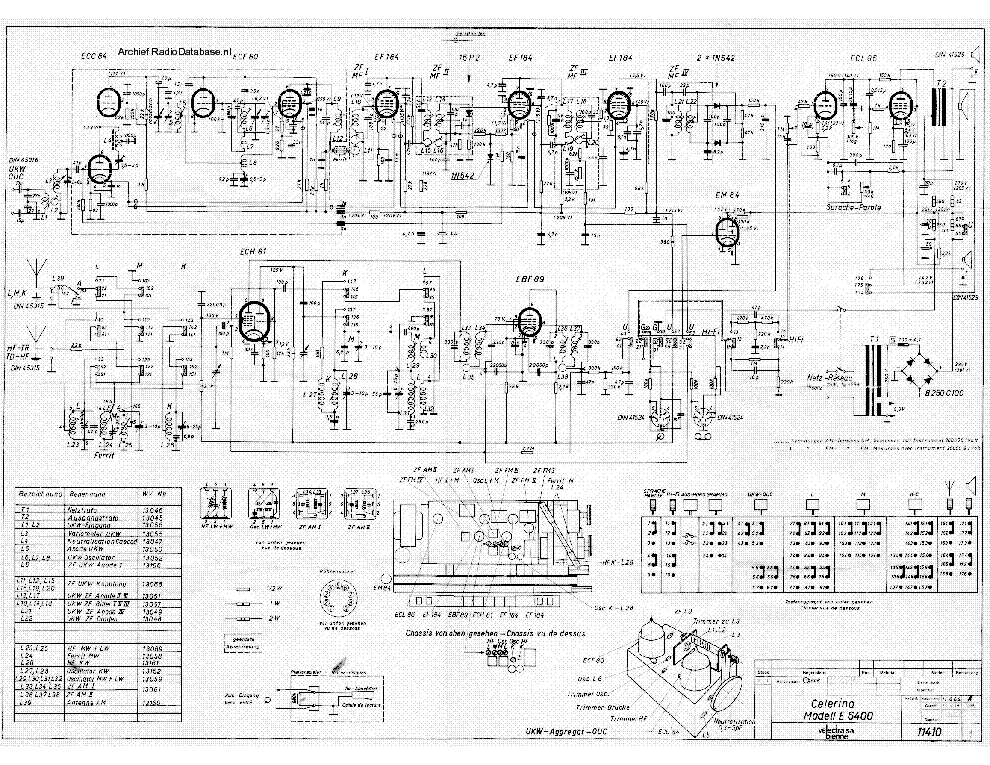
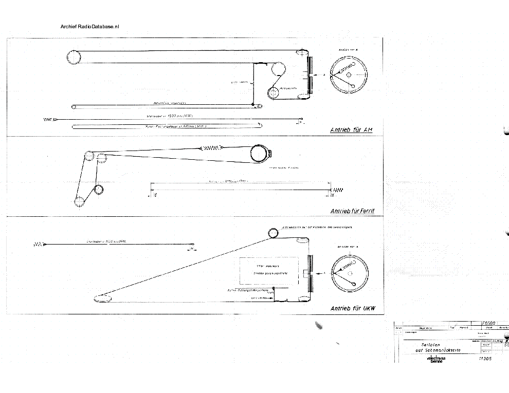
BIENNOPHONE CELERINA E6400 AM-FM RECEIVER 1964 SM

Type:  (PDF)
(PDF)
Size
2.6 MB
2.6 MB
Page
2
2
Category
AUDIO
SERVICE MANUAL
AUDIO
SERVICE MANUAL
If you get stuck in repairing a defective appliance download this repair information for help. See below.
Good luck to the repair!
Please do not offer the downloaded file for sell only use it for personal usage!
Looking for similar biennophone manual?
Good luck to the repair!
Please do not offer the downloaded file for sell only use it for personal usage!
Looking for similar biennophone manual?
Advertisements
Advertisements
Please tick the box below to get download link:
- Also known:
CELERINA E-6400 RECEIVER E6400 AMFM 1964 6400 AM FM AM-FM
- If you have any question about repairing write your question to the Message board. For this no need registration.
- If the site has helped you and you also want to help others, please Upload a manual, circuit diagram or eeprom that is not yet available on the site.
Have a nice Day! - See related repair forum topics below. May be help you to repair.
Warning!
If you are not familiar with electronics, do not attempt to repair!
You could suffer a fatal electrical shock! Instead, contact your nearest service center!
Note! To open downloaded files you need acrobat reader or similar pdf reader program. In addition,
some files are archived,If you are not familiar with electronics, do not attempt to repair!
You could suffer a fatal electrical shock! Instead, contact your nearest service center!
so you need WinZip or WinRar to open that files. Also some files are djvu so you need djvu viewer to open them.
These free programs can be found on this page: needed progs
If you use opera you have to disable opera turbo function to download file!
If you cannot download this file, try it with CHROME or FIREFOX browser.
Translate this page:
Relevant AUDIO forum topics:
Szervusztok !
AKAI DV-R4000VSS házimozi rendszer három hangfala nem szól. A végfokok hűtője letekert hangerőnél is melegszik.Kapcs rajzok keresek, tudna valaki segíteni?
Köszi. Laci
Kedves Tanyalakók!
A fent említett erősítőt kb. egy éve kaptam ajándékba. Az erősítőt azon apropóból vettem elő, hogy
sikerült a Vakerán vennem egy HFM-ReVox A77 RIAA korrektor panelt. Gondoltam meghallgatom, hogy
miért voltak úgy elájulva tőle annak idején a tisztelt HFM munkatársai. Erre a legalkalmasabbnak a
jó öreg AET-250 lett kiszemelve, mivel ebbe könnyű szerrel bele tudom fabrikálni pár másodperc
alatt - gondoltam -, hiszen hely van benne, a szükséges tápfesz is rendelkezésre áll és innen
már akármilyen másik erősítőn keresztül is meg tudom hallgatni. Az első meglepetés akkor ért, amikor
leemeltem a fedelét. Nem is lesz olyan nagyon könnyű beletenni azt az ormótlan nagy panelt. De
sebaj kiveszem a bal végfokot és mindjárt lesz helyem! Amikor elkezdtem a végfokot, elkezdtem
nézegetni, hogy ez meg kiféle-miféle szerkezet, hiszen az AET-250-et nem ilyen végfokkal ismerem.
Hol van ebből a jellegzetes KY dióda? Hiszen ez az eredeti végfok különös ismertetőjegye, no
persze az iszonyatos hangját nem is említve. De biztos már hülyülök, vagy rosszul emlékszem. Elővettem
a '79-es RT évkönyvet, a szerint sem stimmelt a panel. Letöltöttem a gépkönyvét minden fellelhető
forrásból, hátha volt több verzió is. Úgy sem stimmelt. De a vezetékek forrasztásai a másik oldalon
is igencsak gyárinak tűntek. Ezzel félre is tettem és beleeszkabáltam a ReVox korrektort. Nos én
nem ájultam el tőle (szerintem a Yamaha AX500 saját korrektora nagyságrendekkel szebben szól).
Egyszer rászántam magam és lerajzoltam. Utána rögtön láttam, hogy ez a végfok nem is olyan típusidegen
90%-ban megegyezik a még jobban ismert AET-453 végfokjával. Ez csupán pár dologban tér el:
1. Más a negatív visszacsatoló lánc
2. Nincsen benne semilyen védelem sem (de a panelon sincsen helye!!!)
3. A meghajtó tranzisztorok nem a jól ismert BC300-301-303 sorozat, hanem a Siemens BC141-161 párosa
A végtranzisztorai Fairchild gyártmányú 2N3055-7 típusok, ami kísértetiesen hasonlít a régi Motorola
vagy Tesla alukupakos családjára. Mivel a kíváncsiság nagy úr, ezért nagy levegőt vettem és elkezdtem
rendberakni az erősítőt. Az elektrolit kondenzátorok 1975-76-ban készültek. Természetesen ezeket
kicseréltem mind.A potmétereket kipucoltam és ezközöltem rajta 1-2 kisebb finomítást is, de erre
most nem térek ki. Az eredmény egész meghökkentő lett: BEAG erősítőt én még így szólni nem hallottam,
pedig 1-2 típus már árment a kezeim között, sőt rendelkezem is pár típussal. Erre már azt lehet mondani,
hogy egészen hallgatható kis masina!
Az lenne a kérdésem, hogy találkozott már valaki ilyen masinával, vagy tud valamit a történetéről?
Most egy hétig kórházban voltam ezért volt időm megrajzolni számítógépen is az erősítő kapcsrajzát.
Természetesen csak az egyik oldalt rajzoltam meg! A RIAA korrektor, előerősítő megegyezik a klasszikus
AET-250-nel, de a vége inkább az AET-453-mal mutat szoros rokonságot! Jó csemegézést!
Felraktam a módosított verziót is!
Hello everyone,
I've this speaker model:
RCF art 415-A.
The power supply is faulty, no votltage out to the amplifier.
The Mosfets are blown. I've changed the mosfets and it's driver, and still have a problem.
I tried to switch on but only one of the mosfets gets hot (the one which switches the 310. There are 2 of them - Mos5 in the scheme).
Obviously I turned it off.
1) What causes it to heat?
2) Testing the VCC of the LMC555, it's only 2.7V. When taking it out of the circuit, it's 12VDC! What makes the voltage to drop. Where does the supply of the LMC555 come from? The VCC of the 555 should be around 10V, as compared with a good card.
I've changed the 555, but the problem remained. I've checked the components around, resistors and capacitors, and transistors, and seem to be OK.
4) The VCC of the Mosfet driver is 10V, but should be 12V if compared with a good card.
3) Could the trafo be damaged? Are these parts reliable or may blow up?
4) What is the purpose of the optocoupler in the circuit?
I would really appreciate any help.
I didn't find the 100% schemes for this RCF (400), but found a very similar one (The 600 version).
name and a link here to download the pdf.
DigiPRO600B
https://elektrotanya.com/db-technologies_digipro600b_sch.pdf/download.html
Regards and many thanks
Sziasztok!
Szükségem lenne a dynacord gigant v kapcsolási rajzára
Szereztem egy ilyen szép példányt, de hiányzik egy bemeneti, kimeneti panel a hátuljáról. Sajnos az adatbázisban csak a gigant 1 található, ami csöves, ez pedig MJ15003-MJ15004 komplementerrel megy.
Előre is köszi


