Service manuals, schematics, eproms for electrical technicians
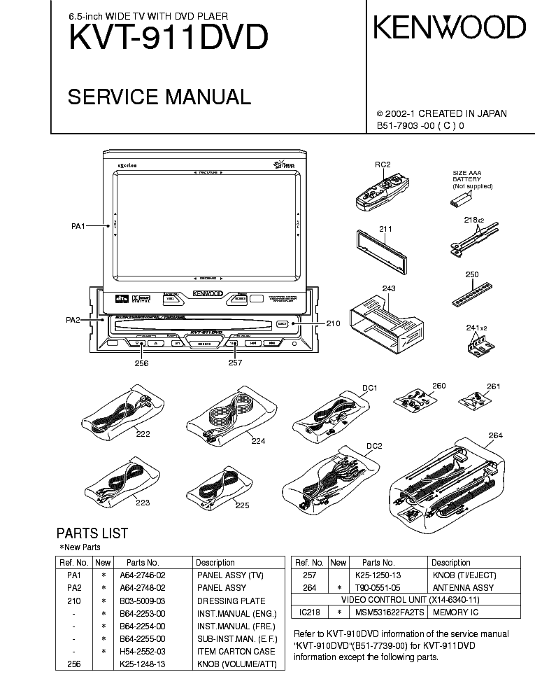
KENWOOD KVT-911

Type:  (PDF)
(PDF)
Size
149.9 KB
149.9 KB
Page
1
1
Category
AUDIO
SERVICE MANUAL
AUDIO
SERVICE MANUAL
If you get stuck in repairing a defective appliance download this repair information for help. See below.
Good luck to the repair!
Please do not offer the downloaded file for sell only use it for personal usage!
Looking for similar kenwood manual?
Good luck to the repair!
Please do not offer the downloaded file for sell only use it for personal usage!
Looking for similar kenwood manual?
Document preview [1st page]

Click on the link for free download!
Advertisements
Download free of charge (10 files / day):

Download processing...

Download processing...
- Also known:
KENWOOD KVT-911 KVT911 KVT 911
- If you have any question about repairing write your question to the Message board. For this no need registration.
- If the site has helped you and you also want to help others, please Upload a manual, circuit diagram or eeprom that is not yet available on the site.
Have a nice Day! - See related repair forum topics below. May be help you to repair.
Warning!
If you are not familiar with electronics, do not attempt to repair!
You could suffer a fatal electrical shock! Instead, contact your nearest service center!
Note! To open downloaded files you need acrobat reader or similar pdf reader program. In addition,
some files are archived,If you are not familiar with electronics, do not attempt to repair!
You could suffer a fatal electrical shock! Instead, contact your nearest service center!
so you need WinZip or WinRar to open that files. Also some files are djvu so you need djvu viewer to open them.
These free programs can be found on this page: needed progs
If you use opera you have to disable opera turbo function to download file!
If you cannot download this file, try it with CHROME or FIREFOX browser.
Translate this page:
Relevant AUDIO forum topics:
Üdvözlet mindenkinek!
A címben említett autórádiónak a kijelzőjén nem látni semmit,a készülék hibátlanul működik az előlapon világítanak a led-ek de kijelzőn nincs semmi.Tud valaki segíteni?Előre is köszönöm
Üdv:Mitu
üdv: Kenwood KCA-BT200 autórádió.keresem ennek az autórádió előlapnak a rajzát
Egy ALPS 8+2 lábú encoder (átmérő 18 mm)van benne, ezt szeretném kimérni.
ALPS katalógusában nem találok ilyent.
kösz,Bálint
Bocs, rossz típusszámot adtak/adtam meg, majd pontosítom.
Ez egy adapter
Bálint
Sziasztok!
Nem tudom mi lehet a gond az erősítő 5csatornás equaliserével.2 db M5227p ic vel van felépítve.Bekapcsolt EQ állapotban az erőlködő egyáltalán nem szól,kikapcsolt(defeat)állásban meg szabályoz(lefelé) az adott EQ frekvenciákon a potit felhúzva gerjed egy szint után.Rajz kellene mert így elég áttekinthetetlen a jel útja.Hanggenerátorral próbáltam követni de már kissé belefáradtam.
Üdv!
Sziasztok!
Csereérett lett a lemezjátszómban a tű, szerintetek mi a különbség ezek közt?
http://www.ebay.com/itm/Needle-Turntable-Kenwood-N-67-N67-Sansui-SN-P212-/261045663066
és
http://www.ebay.com/itm/KENWOOD-SANYO-MARANTZ-SANSUI-TURNTABLE-NEEDLE-STYLUS-819-D7-/270408521961
Similar manuals:
If you want to join us and get repairing help please sign in or sign up by completing a simple electrical test
or write your question to the Message board without registration.
You can write in English language into the forum (not only in Hungarian)!
or write your question to the Message board without registration.
You can write in English language into the forum (not only in Hungarian)!
E-Waste Reduce


