Service manuals, schematics, eproms for electrical technicians
METRA PK100 USER MANUAL

Type:  (PDF)
(PDF)
(PDF)Size
6.3 MB
6.3 MB
Page
2
2
Category
METER
USER MANUAL
METER
USER MANUAL
If you get stuck in repairing a defective appliance download this repair information for help. See below.
Good luck to the repair!
Please do not offer the downloaded file for sell only use it for personal usage!
Looking for similar metra manual?
Good luck to the repair!
Please do not offer the downloaded file for sell only use it for personal usage!
Looking for similar metra manual?
Advertisements
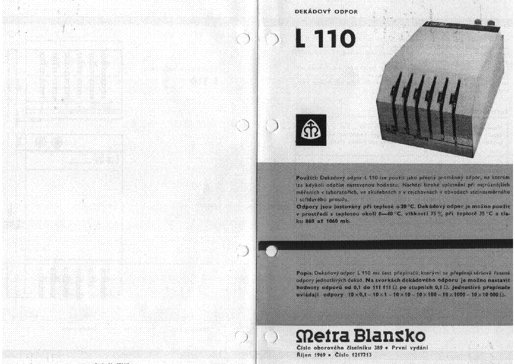
Document preview [1st page]

Click on the link for free download!
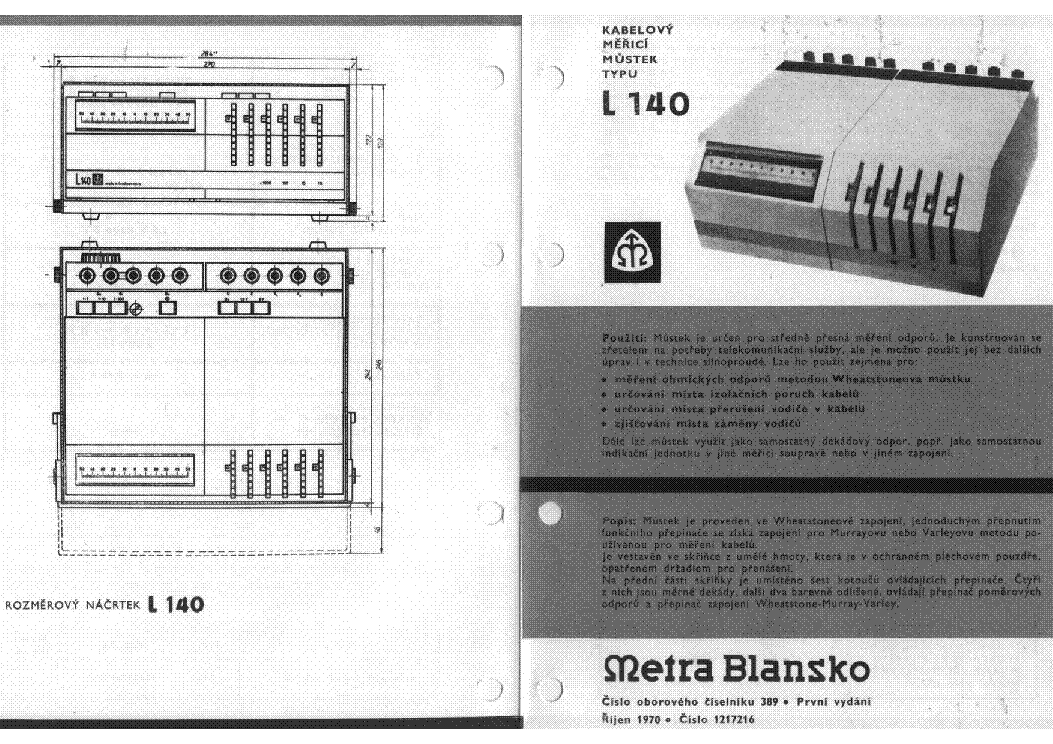
Document preview [2nd page]

Click on the link for free download!
Advertisements
Please tick the box below to get download link:
- Also known:
METRA PK-100 PK100 PK 100
- If you have any question about repairing write your question to the Message board. For this no need registration.
- If the site has helped you and you also want to help others, please Upload a manual, circuit diagram or eeprom that is not yet available on the site.
Have a nice Day! - See related repair forum topics below. May be help you to repair.
Warning!
If you are not familiar with electronics, do not attempt to repair!
You could suffer a fatal electrical shock! Instead, contact your nearest service center!
Note! To open downloaded files you need acrobat reader or similar pdf reader program. In addition,
some files are archived,If you are not familiar with electronics, do not attempt to repair!
You could suffer a fatal electrical shock! Instead, contact your nearest service center!
so you need WinZip or WinRar to open that files. Also some files are djvu so you need djvu viewer to open them.
These free programs can be found on this page: needed progs
If you use opera you have to disable opera turbo function to download file!
If you cannot download this file, try it with CHROME or FIREFOX browser.
Translate this page:
Relevant METER forum topics:
Hi All
Please Help !
my Atten ADS1022C+ not work after firmware upgrade ((
I have only flash dump from ADS1102CAL (7" display)
after flash this dump, i upgrade original Atten ADS1000 series firmware from USB, and get an almost working DSO
due to non-compliance hardware ((
I need Atten ADS1022..ADS1042..ADS1062 or Siglent SDS1022C Flash dump.
and Siglent SDS1022C latest Firmware
The owner of this oscilloscope can not only help me, but also protect yourself by making a dump of your firmware.. All you need to download the firmware DUMP via JTAG is here https://cloud.mail.ru/public/D9hP/vaBkzVoyT
Sziasztok
Szert tettem egy Normameter GW műszerre. A mutatója el volt törve, azt sikerült kicserélni, de akad. Azt szeretném megtudni mivel lehetne letisztítani a mágnest.
Köszönöm.
Szkóp hitelesítés
D10 170GH vagy 270-es csövet keresek!
Similar manuals:


If you want to join us and get repairing help please sign in or sign up by completing a simple electrical test
or write your question to the Message board without registration.
You can write in English language into the forum (not only in Hungarian)!
or write your question to the Message board without registration.
You can write in English language into the forum (not only in Hungarian)!
E-Waste Reduce