Service manuals, schematics, eproms for electrical technicians
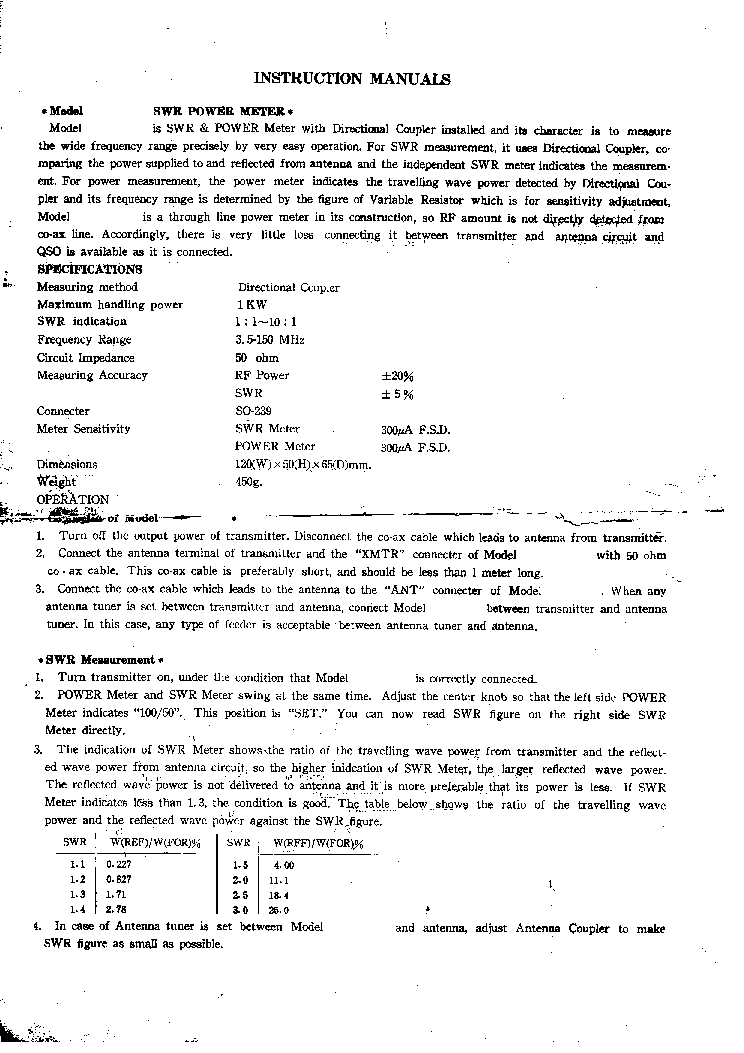
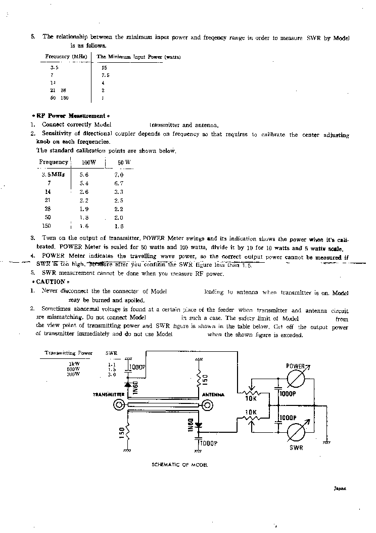
QUEMENT SWB-3 STANDING WAVE BRIDGE AND POWER INDICATOR

Type:  (PDF)
(PDF)
Size
779.9 KB
779.9 KB
Page
3
3
Category
METER
SERVICE MANUAL
METER
SERVICE MANUAL
If you get stuck in repairing a defective appliance download this repair information for help. See below.
Good luck to the repair!
Please do not offer the downloaded file for sell only use it for personal usage!
Looking for similar quement manual?
Good luck to the repair!
Please do not offer the downloaded file for sell only use it for personal usage!
Looking for similar quement manual?
Advertisements
Advertisements
Please tick the box below to get download link:
- Also known:
QUEMENT SWB-3 WAVE BRIDGE AND POWER INDICATOR SWB3 STANDING SWB
- If you have any question about repairing write your question to the Message board. For this no need registration.
- If the site has helped you and you also want to help others, please Upload a manual, circuit diagram or eeprom that is not yet available on the site.
Have a nice Day! - See related repair forum topics below. May be help you to repair.
Warning!
If you are not familiar with electronics, do not attempt to repair!
You could suffer a fatal electrical shock! Instead, contact your nearest service center!
Note! To open downloaded files you need acrobat reader or similar pdf reader program. In addition,
some files are archived,If you are not familiar with electronics, do not attempt to repair!
You could suffer a fatal electrical shock! Instead, contact your nearest service center!
so you need WinZip or WinRar to open that files. Also some files are djvu so you need djvu viewer to open them.
These free programs can be found on this page: needed progs
If you use opera you have to disable opera turbo function to download file!
If you cannot download this file, try it with CHROME or FIREFOX browser.
Translate this page:
Relevant METER forum topics:
Hi,
I have got TR-0467 that needs repairment.
I also have got Hungarian version of it's service manual but (I am very sorry) I do not read Hungarian.
My copy needs a password to be copied and I do not know it. I downloaded it from Elektrotanya.
Is it any good soul out there with English version of the said manual? Or with not encoded pdf Hungarian version?
It would save me a lot of time on rewriting Hungarian text in order to translate it with Google translator.
Thanks in advance...
Zbig
szarycz at hotmail com
Szevasztok tudnátok nekem segiteni kellene valamien prog ramozó rajz amivel tudnék epromokat beirni, na és persze egy leirés hogy hogyan is használjam mert eddig máshoz mentem ha törlődött valami, deha már van nak prog ramok és van gép is akkor én is megpróbálkoznék épiteni,egy sajátot.
Olá amigos, alguem tem uma foto da posiçao dos contatos do seletor pois desmontei a mesma e escapou os contatos da chave e nunca mais acertei.
Agradeço a todos.
Trata-se de um multimetro taiwan modelo 5175XL de cor beje mas não tenho mais referencias do fabricante ou manual eletrico quanto menos, posiçao das chaves.
Tentei posicionar os contatos baseados no multimetro da Icel mas sem sucesso.
Agradeço a todos.
Trata-se de um multimetro taiwan modelo 5175XL de cor beje mas não tenho mais referencias do fabricante ou manual eletrico quanto menos, posiçao das chaves.
Tentei posicionar os contatos baseados no multimetro da Icel mas sem sucesso.
Üdvözlöm a fórum tagjait!
A RT 1993/5. számban megjelent egy 100 MHz-es frekvenciamérő kapcsolási rajza és paneltervei.
A paneltervet megrajzolva felfigyeltem egy problémára: a kapcsolási rajz nincs összhangban a paneltervvel.
Tulajdonképpen probléma a következőktől kezdődik:
- az IC14 CD4543 "A" 5-ös láb összekötése az IC8 CD4518 "QA" 3-as láb összekötése
- az IC13 CD4543 "A" 5-ös láb összekötése az IC8 CD4518 "QA" 11-es láb összekötése
- az IC14 CD4543 "D" 4-es láb összekötése az IC8 CD4518 "QD" 6-os láb összekötése
- az IC13 CD4543 "D" 4-ös láb összekötése az IC8 CD4518 "QD" 14-es láb összekötése
Eddig leírtak szerint az SCH megegyezik a PCB rajzolatával.
Innentől a tényleges probléma:
Az SCH alapján az R17-es ellenállás az IC14 CD4543 "A" 5-ös láb valamint az IC8 CD4518 "QA" 3-as lábhoz kapcsolódik,
a PCB alapján pedig az IC14 CD4543 "D" 4-es láb valamint az IC8 CD4518 "QD" 6-os lábhoz kapcsolódik.
Az SCH alapján az IC8 CD4518 2-es láb az IC13 CD4543 "A" 5-ös láb valamint az IC8 CD4518 "QA" 11-es lábhoz kapcsolódik
a PCB alapján pedig az IC13 CD4543 "D" 4-ös láb valamint az IC8 CD4518 "QD" 14-es lábhoz kapcsolódik
Az SCH alapján az IC8 CD4518 10-es láb az IC12 CD4543 "A" 5-ös láb valamint az IC7 CD4518 "QA" 3-as lábhoz kapcsolódik
a PCB alapján pedig az IC8 CD4518 10-es láb az IC12 CD4543 "D" 4-es láb valamint az IC7 CD4518 "QD" 6-os lábhoz kapcsolódik
...
...
Ezek a hibák folyamatosak a CD4543-as és a CD4518 IC-k között - csak az A-QA és a D-QD összekötésekhez kapcsolódóan nem egyezik az eredeti SCH alapján megtervezett PCB.
A fentiekben leírtak alapján melyik a jó: eredeti SCH vagy az eredeti PCB terv?
Válaszokat előre is köszönöm.


