Service manuals, schematics, eproms for electrical technicians
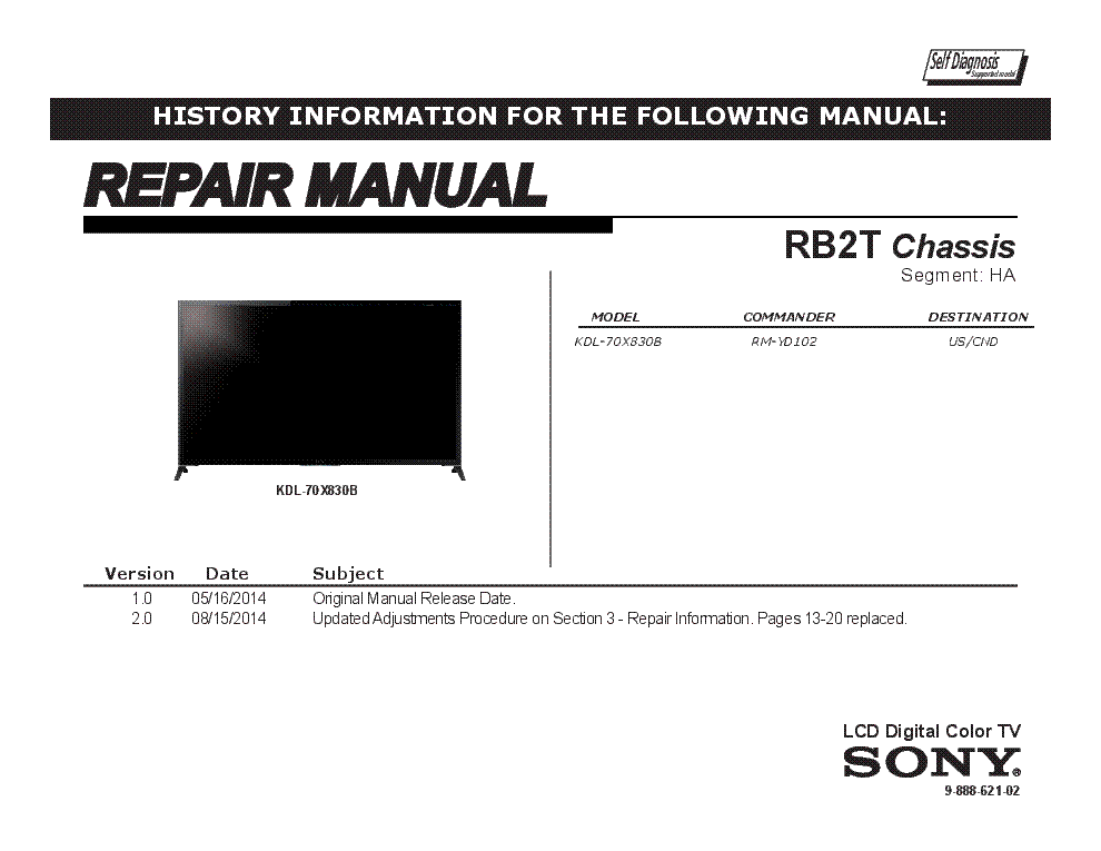
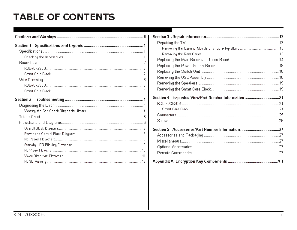
SONY KDL-70X830B CHASSIS RB2T VER.2.0 SEGM.HA RM

Type:  (PDF)
(PDF)
Size
12.9 MB
12.9 MB
Page
32
32
Category
TV
SERVICE MANUAL
TV
SERVICE MANUAL
If you get stuck in repairing a defective appliance download this repair information for help. See below.
Good luck to the repair!
Please do not offer the downloaded file for sell only use it for personal usage!
Looking for similar sony manual?
Good luck to the repair!
Please do not offer the downloaded file for sell only use it for personal usage!
Looking for similar sony manual?
Advertisements
Advertisements
Please tick the box below to get download link:
- Also known:
SONY CHASSIS RB-2T RM KDL70X830B RB2T SEGM.HA KDL 70 830 RB 70X830B
- If you have any question about repairing write your question to the Message board. For this no need registration.
- If the site has helped you and you also want to help others, please Upload a manual, circuit diagram or eeprom that is not yet available on the site.
Have a nice Day! - See related repair forum topics below. May be help you to repair.
Warning!
If you are not familiar with electronics, do not attempt to repair!
You could suffer a fatal electrical shock! Instead, contact your nearest service center!
Note! To open downloaded files you need acrobat reader or similar pdf reader program. In addition,
some files are archived,If you are not familiar with electronics, do not attempt to repair!
You could suffer a fatal electrical shock! Instead, contact your nearest service center!
so you need WinZip or WinRar to open that files. Also some files are djvu so you need djvu viewer to open them.
These free programs can be found on this page: needed progs
If you use opera you have to disable opera turbo function to download file!
If you cannot download this file, try it with CHROME or FIREFOX browser.
Translate this page:
Relevant TV forum topics:
Üdv!
Fenti készülék bekapcsol, de a led háttér világítása nem megy. A két csík teszterrel egyenként mérve 55V-on szépen működik. A táp felől viszont csak 64V-ot kap (ennyi a max bejövő is, a FET és a source kör rendben) és mivel soba vannak kötve ez nagyon kevés. Ha a csíkokat egyenként kötöm be, működnek, nem tilt le a védelem.
Hol lehet a hiba?
Sziasztok!
Már másodszor hozzák vissza..
Valamikor jó akár 2 napig is, nem elkó hiba lehet, mert volt hogy este kihuztam a 230V-ból, 1 napra rá bekapcsolom és mukodik. Szolok a gazdajanak hogy jöhet, nem kapcsol be.
Atcineztem már sok mindent táp/proci/csatlakozo/trafolab, de nem kontakt hiba lehet mert van ugy hogy mozdulatlanul mukodik kikapcsolom es 1 h mulva nem kapcsol be.
Ha mukodik 5 percig akkor lehetséges hogy egész nap mukodni fog.
Amikor nem mukodik akkor akarmeddig be lehet dugva a konektorba, nem fog bekapcsolni kikapcsolas után, áramtalanitani kell órákig, azután vagy bekapcsol vagy nem.
Utoljara már ugy kapcsoltam be két esetben is, hogy a demagnetizalo tekercset kihuztam, és azutan bekapcsolt. De lehet hogy véletlen volt.
PTC-t is csereltem már.
Amikor nincs stby led, attol még megvannak a stby szekunder tápfeszultségek, nem tudom pontosan mennyi kell hogy legyen stby-ban mert gyorsan megjavul a TV és nincs mit mérjek a jó TV-n.
Ha taviranyitoval kapcsoljak ki akkor jo marad, de a tulaj rossz idokre hivatkozva esténként a nagy gombbal kikapcsolja..
Nem tudom eldonteni merre méregessek primer/sekunder/ vagy proci
Primerben nem találtam hibát..
Sziasztok!
A fent említett Full HD-s LED Smart Tv egy munkatársamé. Elmondása szerint otthon a Tv ajánlatára elindította a frissítést, majd a végén fekete kép fogadta. Áramtalanítás után is a Tv nem áll meg stand by üzemmodban, hanem egyből be is kapcsol. A képen pici villogást lehet látni (gondolom a háttérvilágítás), de továbbá semmi, se kép, se hang vagy valami üzenet.
Lehet ezt otthoni körülmények között orvosolni, vagy csak szervíz.
Köszönöm!
mitibi
Hello
I have on my table this sony kdl32ex600 with backlight issue. It's a common failure of this psu but i do not find any part faulted on this board.
The schematic it is almost the same, with minor differences with GE3B found at page 56 on this service manual:
https://elektrotanya.com/sony_kdl-32ex600_kdl-40ex600_kdl46ex600_chassis_az1-k.pdf/download.html
Uploaded only the page 56 from this sm to easing the search.
The red led it's flashing 2 times, meaning psu faulty. Indeed the led backlight does not light.
With the PSU outside of the tv, just with one resistance of 180ohm between standby ( pin 1 3,3V on connector CN6150 ) i get this values
on in:
starting with pin 1
1 +3,3V ST-BY
2 +3,3V AC_OFF_DET
3 +3,3V POWER_ON (with resistance 180ohm between pin1 and pin 3)
4 +12,56V AUDIO_12V
5 0V AUDIO_12V_GND
6 0V REG_12V_GND
7 0V REG_12V_GND
8 +12,6V REG_12V
9 +12,6V REG_12V
10 +0,1V BL_ERR
11 +3,3V BL_ON
12 0V DIMMER
13 0V DIMMER_DC
14 0V T-CON_Vcc_12V
15 0V T-CON_ON
All measure done at secondary ground point C6800 GND as reference.
Meanwhile, the led connected to CN6800 will remain with no light at all. The CN6800 will deliver positive 91V.
The negative branch will deliver at CN6801 ( both pin1 & 2 ) just -1V.
In the training manual found always in here at
https://elektrotanya.com/sony_kdl-32ex600_40ex600_46ex600_chassis_az1k_training%20manual.pdf/download.html
at page 56 will say "SHORT" at pin 12 DIMMER for testing the PSU, always with pin 3 POWER_ON connected to 3,3V ST-BY - pin1.
If i'll put a 180ohm resistance between GND and pin 12 DIMMER, then the tension on CN6800 will rise to +179V and the negative from the CN6801 will rise to -5V, the backlight led will light very very weak.
All tension from CN6805 will remain the same, except the BL_ERR will rise from +0,1V to +1,1V.
With only power_on pin 3 shorted by 180ohm resistance to the pin 1, i get this weak oscillation at emiter of Q6816 + Q6817
[URL=https://picturepush.com/public/16067400][IMG]https://www1.picturepush.com/photo/a/16067400/640/diverse/Q6816Q6817.jpg[/IMG][/URL]
With pin 12 DIMMER shorted ( always by a 180ohm resistance ) at GND, the oscillation will change from 250khz 1,6vpp to almost 70khz at 0,81Vpp. as below:
[URL=https://picturepush.com/public/16067401][IMG]https://www1.picturepush.com/photo/a/16067401/640/diverse/20181117-175255.jpg[/IMG][/URL]
Already checked the capacitors C6828 / C6830 together with D6805 / D6806.
Also checked the L6800 ( trafo ) and i've get 5,5mH instead of 5mH, i think it's ok.
All fuse checked, ok.
Q6814 and Q6801 tested under mosfet tester, ok.
[url=https://picturepush.com/public/16067402][img=https://www1.picturepush.com/photo/a/16067402/220/16067402.jpg][/url]
IC6800 & IC6801 gave +9V and respectively +2,49V
Already checked various components all over the board, i am out of ideas.
Any idea or help would be apreciated.
Similar manuals:
If you want to join us and get repairing help please sign in or sign up by completing a simple electrical test
or write your question to the Message board without registration.
You can write in English language into the forum (not only in Hungarian)!
or write your question to the Message board without registration.
You can write in English language into the forum (not only in Hungarian)!
E-Waste Reduce


