Service manuals, schematics, eproms for electrical technicians
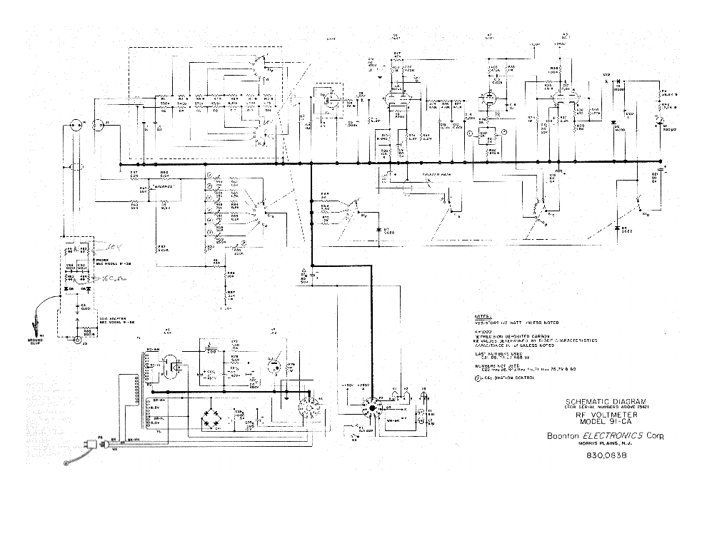
BOONTON MODEL 91-CA RF VOLTMETER SCH

Type:  (PDF)
(PDF)
Size
1.2 MB
1.2 MB
Page
1
1
Category
METER
SERVICE MANUAL
METER
SERVICE MANUAL
If you get stuck in repairing a defective appliance download this repair information for help. See below.
Good luck to the repair!
Please do not offer the downloaded file for sell only use it for personal usage!
Looking for similar boonton manual?
Good luck to the repair!
Please do not offer the downloaded file for sell only use it for personal usage!
Looking for similar boonton manual?
Document preview [1st page]

Click on the link for free download!
Advertisements
Please tick the box below to get download link:
- Also known:
BOONTON MODEL RF 91CA 91 CA 91-CA
- If you have any question about repairing write your question to the Message board. For this no need registration.
- If the site has helped you and you also want to help others, please Upload a manual, circuit diagram or eeprom that is not yet available on the site.
Have a nice Day! - See related repair forum topics below. May be help you to repair.
Warning!
If you are not familiar with electronics, do not attempt to repair!
You could suffer a fatal electrical shock! Instead, contact your nearest service center!
Note! To open downloaded files you need acrobat reader or similar pdf reader program. In addition,
some files are archived,If you are not familiar with electronics, do not attempt to repair!
You could suffer a fatal electrical shock! Instead, contact your nearest service center!
so you need WinZip or WinRar to open that files. Also some files are djvu so you need djvu viewer to open them.
These free programs can be found on this page: needed progs
If you use opera you have to disable opera turbo function to download file!
If you cannot download this file, try it with CHROME or FIREFOX browser.
Translate this page:
Relevant METER forum topics:
Sziasztok
Szeretném felújítani a fenti remek kis műszerem.
Az elektronikát megjavítottam, de sajnos a skála felirat lekopott az olvashatatlanságig.
Ha valaki megtenné, hogy lefényképezi és elküldené nekem, nagyon örülnék.
Köszi
Szabi
Sziasztok Mesterek! Tisztelettel kérdezném főleg az idősebb szakikat,hogy ismeri valaki ezt a nagyon régi oszcilloszkópot? Úgy két éve került a gyűjteményembe sajnos azóta sem sikerült róla megtudnom semmit. A adattáblán annyi van:TYPE:1KO/712/ON.Úgy tippelném hogy az ötvenes évek elején készülhetett,az elején orosz feliratok,Magyar Posta bemérő cimke rajta, és tele RFT alkatrészekkel.A csőkészlet:
EF 14 6darab
EZ 12 2darab
RFG 5 1darab
EL 11 3darab
Bár az egyik cső rendetlenkedik de egyébként működik is. Ha valaki tud valami infót erről a műszerről kérem irja meg.
Tisztelettel köszönöm a válaszokat pali
Sziasztok!
Szeretném kérdezni, hogy a Ganzuniv 2 skálatükrét lehet-e cserélni? Az idő múlásával homályos lett.
Köszönettel:Falus Áron
In my case the display of the ScopeMeter was frozen and the keyboard did not respond any more exept the on/off key. This happened always after the ScopeMeter has been switched on for a while. To find the temperature effect, I heated up the different parts of the Digital A1 board with a hair dryer. At some point, the device display stopped working completely and only the backlight was working. This effect was steady and irreversible.
To repair the device, you need the "fluke_92b_96b_99b_105b_servicemanual" provided here in the service manual area.
On page 272 in Figure 9.2b (Digital A1 circuit diagram, part b) the display contrast circuit schematic shows the NPN Transistor V1432 of type BC848C (see also the attached picture). Measuring the Base/Emitter diode showed a low resistance of 100 Ohms in both directions. Replacing that transistor by a NPN transistor of type BC847C solved the problem and the device was working correctly again.
The reason for choosing the BC847C instead of the BC848C are the Vcbo and Vceo of only 30 V of the BC848x series. The BC847x series has a Vcbo of 50 V and a Vceo of 45 V respectively and offers therefore a greater margin. The V1432 is placed between TP431 (LCDPWR, +5 V) and the -30 V connection from Analog Board A2. These conditions are too close to the absolute maximum ratings of the BC848x and are especially for higher temperatures critical.
Similar manuals:
If you want to join us and get repairing help please sign in or sign up by completing a simple electrical test
or write your question to the Message board without registration.
You can write in English language into the forum (not only in Hungarian)!
or write your question to the Message board without registration.
You can write in English language into the forum (not only in Hungarian)!
E-Waste Reduce


