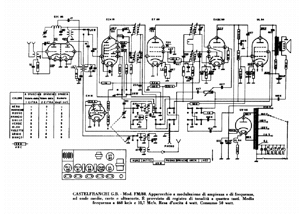
CASTELFRANCHI SM1254 AM-FM RADIO RECEIVER SCH

 (PDF)
(PDF)154.6 KB
1
AUDIO
SERVICE MANUAL
Good luck to the repair!
Please do not offer the downloaded file for sell only use it for personal usage!
Looking for similar castelfranchi manual?

Click on the link for free download!
- Also known:
SM-1254 RADIO RECEIVER SM1254 AMFM 1254 AM FM AM-FM
- If you have any question about repairing write your question to the Message board. For this no need registration.
- If the site has helped you and you also want to help others, please Upload a manual, circuit diagram or eeprom that is not yet available on the site.
Have a nice Day! - See related repair forum topics below. May be help you to repair.
If you are not familiar with electronics, do not attempt to repair!
You could suffer a fatal electrical shock! Instead, contact your nearest service center!
so you need WinZip or WinRar to open that files. Also some files are djvu so you need djvu viewer to open them.
These free programs can be found on this page: needed progs
If you use opera you have to disable opera turbo function to download file!
If you cannot download this file, try it with CHROME or FIREFOX browser.
Egy viharvert Aurex Toshiba SC V50 erősítő került a kezembe azzal, hogy végfok hibás. Azt meg is javítottam annak rendje és módja szerint, miután eltávolítotam a kb 100A-es sodrott vezetéket a biztosíték helyéről, és megjavítottam a zárlatos végfokot. Szépen beállt a középponti 0V feszültség, de a kijelző sötét maradt. Föltettem a SM-keresőbe a rajz keresést, de sajnos nincs eredmény.
Tudna valaki segíteni tanáccsal, esetleg rajzzal?
Köszönettel:
Attila
A kérdés megoldódott:
A segédtáp 10ohm-os biztosítékellenállása megszakadt.
Köszönöm a hozzászólásokat!
Üdvözlettel:
Attila
This is a compact design to I guess transfer the vinyl into MP3 format.
Complaint was when the arm was moved the tt dont spin, confirmed that as
theres a leaf switch to sense arm movement,
and its fed to a main pcb with all the IC's that I guess handle all the
stuff. The switch is ok, and I remember seeing 14V or so on the motor pins
frm the PCB, so I figured perhaps theres anough current to spin the motor and
focused on testing the motor.
Manufacturer does not supply the mainboard that feeds the motor but
the motor can be taken apart and after I opened it and
disconnected the small pcb fron the motor terminals and apply power
directly, it spins w 12v. theres a small electrolytic cap on the pcb 25V / 22uF and an
AN6652 4 pin T0-220 type case IC that I guess is some kind of speed control
circuitry.
The drive Motor is an EG-530-SD-3F, main board is stamped K-13007.
Gonna check the cap, but after searching this IC and its
applications with the motor, I see its popular and some drawings show how its used to regulate the 78,33
and 45 rpm speeds.
This drawing looks pretty much what I see in there:
https://tectronelectronics.eu/images/thumbnails/465/465/detailed/31/eg530.jpg
I have replaced the IC and the cap, but the motor still does not turn. The main pcb
is proprietary and cant be purchased, and I think it is giving the op-amp IC a reference signal.
Is there a way to bypass that signal or fool the IC to believing its on to test it out?
Photo showing the motor pcb :
http://www.mediafire.com/view/s79blgku1503mtg/HPIM0643.JPG/file
Photo of motor under test:
http://www.mediafire.com/view/thhgvcwac8al7gu/HPIM0635.jpg/file
or write your question to the Message board without registration.
You can write in English language into the forum (not only in Hungarian)!