Service manuals, schematics, eproms for electrical technicians
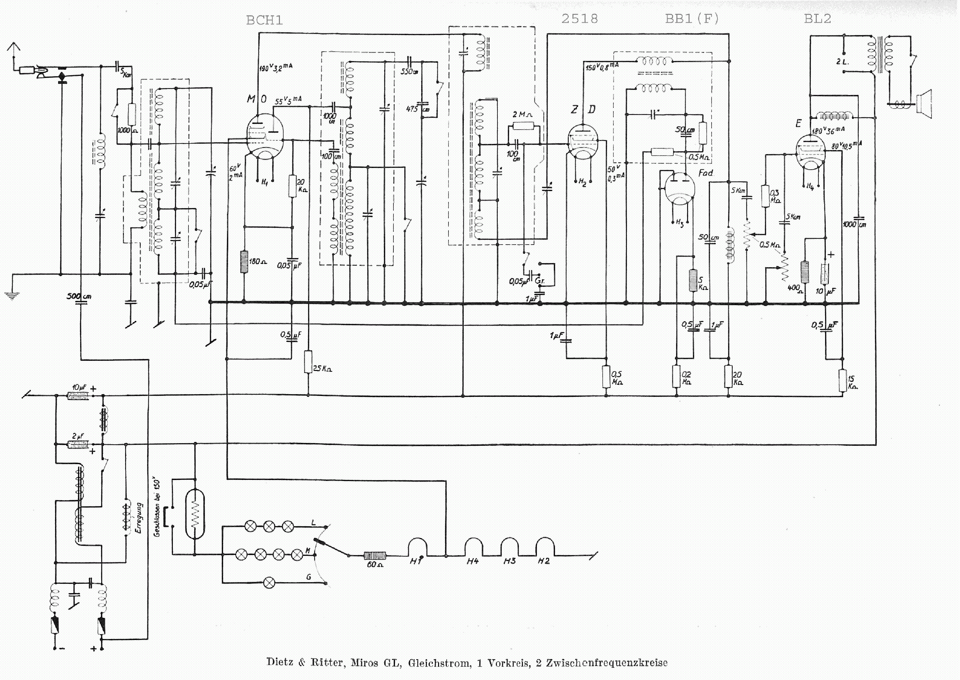
KORTING MIROSGL

Type:  (PDF)
(PDF)
Size
238.8 KB
238.8 KB
Page
1
1
Category
AUDIO
SERVICE MANUAL
AUDIO
SERVICE MANUAL
If you get stuck in repairing a defective appliance download this repair information for help. See below.
Good luck to the repair!
Please do not offer the downloaded file for sell only use it for personal usage!
Looking for similar korting manual?
Good luck to the repair!
Please do not offer the downloaded file for sell only use it for personal usage!
Looking for similar korting manual?
Document preview [1st page]

Click on the link for free download!
Advertisements
Please tick the box below to get download link:
- Also known:
KORTING MIROSGL
- If you have any question about repairing write your question to the Message board. For this no need registration.
- If the site has helped you and you also want to help others, please Upload a manual, circuit diagram or eeprom that is not yet available on the site.
Have a nice Day! - See related repair forum topics below. May be help you to repair.
Warning!
If you are not familiar with electronics, do not attempt to repair!
You could suffer a fatal electrical shock! Instead, contact your nearest service center!
Note! To open downloaded files you need acrobat reader or similar pdf reader program. In addition,
some files are archived,If you are not familiar with electronics, do not attempt to repair!
You could suffer a fatal electrical shock! Instead, contact your nearest service center!
so you need WinZip or WinRar to open that files. Also some files are djvu so you need djvu viewer to open them.
These free programs can be found on this page: needed progs
If you use opera you have to disable opera turbo function to download file!
If you cannot download this file, try it with CHROME or FIREFOX browser.
Translate this page:
Relevant AUDIO forum topics:
Trying to troubleshoot a issue with this radio and there are some SM / schematics on some websites,
but they are slightly different than this one.
Would anyone know a place to look where there are some Grundig people familiar with the products?
but they are slightly different than this one.
Would anyone know a place to look where there are some Grundig people familiar with the products?
Kedves Hozzáértők!
Segítséget kérek a lemezjátszóm témájában. A címben szereplő lemezjátszót megmentettem az enyészettől (bevallom kukáztam, de még a kidobó kezéből sikerült kivennem). Darabokban volt, összeraktam. Tettem bele Ortofon OM-5-ös pick-up-ot. Lecseréltem a DIN csatlakozóját RCA-ra.
Működik, szól, de amivel nem tudok mit kezdeni, az az, hogy brummot küld az erősítő bemenetére. Ha be van dugva, de még nincs bekapcsolva már akkor is, elég nagy jelszinttel. Ha bekapcsolom, akkor leesik a brumm szintje, a hasznos jel aránylag el is nyomja, de akkor is észrevehetően ott van.
Észre vettem, hogy javítás közben a mechanika test vezetéke leszakadt. Visszaforrasztorttam, de nem lett ettől kissebb a brumm szintje.
Készítettem egy földelő kábelt, amivel az erősítő dedikált test pontját lekötöttem a konnektor föld pontjára. Ez sem igazán segített. Mondjuk a lakásban nincs igazi föld, mert a betápnál össze van közösítve a konnektorok összegyűjtött földvezetékei a nullával (lakótelepi lakás).
Az egész jelenségben azt nem értem a leginkább, hogy mitől csökken le a brumm szintje, amikor bekapcsolom a lemezjátszó motorját. A motor áramköreinek semmi köze a hangszedőhöz, teljesen szét vannak választva elektromosan/galavanitikusan.
Van erre valakinek használható ötlete?
Előre is köszönöm!
Gábor
A témát továbbképzés szükségessége miatt feleslegesnek és lezártnak tekintem.
Köszönöm!
Gábor
Megoldás: A lemezjátszónak jót tett a sok törődés, de alapvetően az erősítő felett trónoló CRT TV elektromágneses zaja akasztotta ki a PHONO bemenetet. Áramtalanított TV mellett szépen elcsendesedett a zaj.
Eladók a képen látható kisméretű hangszórók 800ft/db áron,szinte újak.5db van belőlük,ha 4-et megveszel az 5. ajándék!
Árnyékolt mágneskör 8cm ,20w és 4ohm
Want to share:
Have downloaded the schematics from this forum to help repair the amplifier of a friend.
Turned out that Sony decided to route the earth through the chassis, even the earth between the various supplies.
When one takes the main board out of the chassis and switches the amp on, there are up to 20 volts difference between the eart (and hence reference) of the pre-amps and the main amps.
Luckily the amp goes into protection but from a design point of view it is not nice to rely on screws and aluminum face plates to conduct up to 0.2 amps of current from one supply to another.
What I did is solder wires to every eart point and connected them on the main board to make it stand alone and not rely on conducting current through the chassis anymore.
Bad design, simple repair but took some digging in the schematics to find out what exactly was going on!
Similar manuals:
If you want to join us and get repairing help please sign in or sign up by completing a simple electrical test
or write your question to the Message board without registration.
You can write in English language into the forum (not only in Hungarian)!
or write your question to the Message board without registration.
You can write in English language into the forum (not only in Hungarian)!
E-Waste Reduce


