Service manuals, schematics, eproms for electrical technicians
MP-2 TUBE MAGNETOPHONE SCH.

Type:  (DJVU)
(DJVU)Size
16.7 KB
16.7 KB
Page
---
---
Category
AUDIO
SERVICE MANUAL
AUDIO
SERVICE MANUAL
If you get stuck in repairing a defective appliance download this repair information for help. See below.
Good luck to the repair!
Please do not offer the downloaded file for sell only use it for personal usage!
Looking for similar mp manual?
Good luck to the repair!
Please do not offer the downloaded file for sell only use it for personal usage!
Looking for similar mp manual?
Document preview [1st page]

No preview item for this file.
Possible causes:
- No preview picture generated yet.
- It is not a pdf file.
Advertisements
Please tick the box below to get download link:
- Also known:
MP-2 SCH. MP2 TUBE MP
- If you have any question about repairing write your question to the Message board. For this no need registration.
- If the site has helped you and you also want to help others, please Upload a manual, circuit diagram or eeprom that is not yet available on the site.
Have a nice Day! - See related repair forum topics below. May be help you to repair.
Warning!
If you are not familiar with electronics, do not attempt to repair!
You could suffer a fatal electrical shock! Instead, contact your nearest service center!
Note! To open downloaded files you need acrobat reader or similar pdf reader program. In addition,
some files are archived,If you are not familiar with electronics, do not attempt to repair!
You could suffer a fatal electrical shock! Instead, contact your nearest service center!
so you need WinZip or WinRar to open that files. Also some files are djvu so you need djvu viewer to open them.
These free programs can be found on this page: needed progs
If you use opera you have to disable opera turbo function to download file!
If you cannot download this file, try it with CHROME or FIREFOX browser.
Translate this page:
Relevant AUDIO forum topics:
Hello
PMP5000 keverőpult mono csatornáin 1-12 a gain csak az utolsó 5 % ban szabályoz.Találkoztatok e ezzel a problémával?
A +-15V táp rendben van. Labortáppal próbáltam.
PMP5000 keverőpult mono csatornáin 1-12 a gain csak az utolsó 5 % ban szabályoz.Találkoztatok e ezzel a problémával?
A +-15V táp rendben van. Labortáppal próbáltam.
The Mission Cyrus 1 service information in the Internet did not include the PCB nor the voltages so far.
It is a bit difficult for you guys to repair it.
I have just repaired one and I took the time to redraw the PCB and measured the voltage to ease your job.
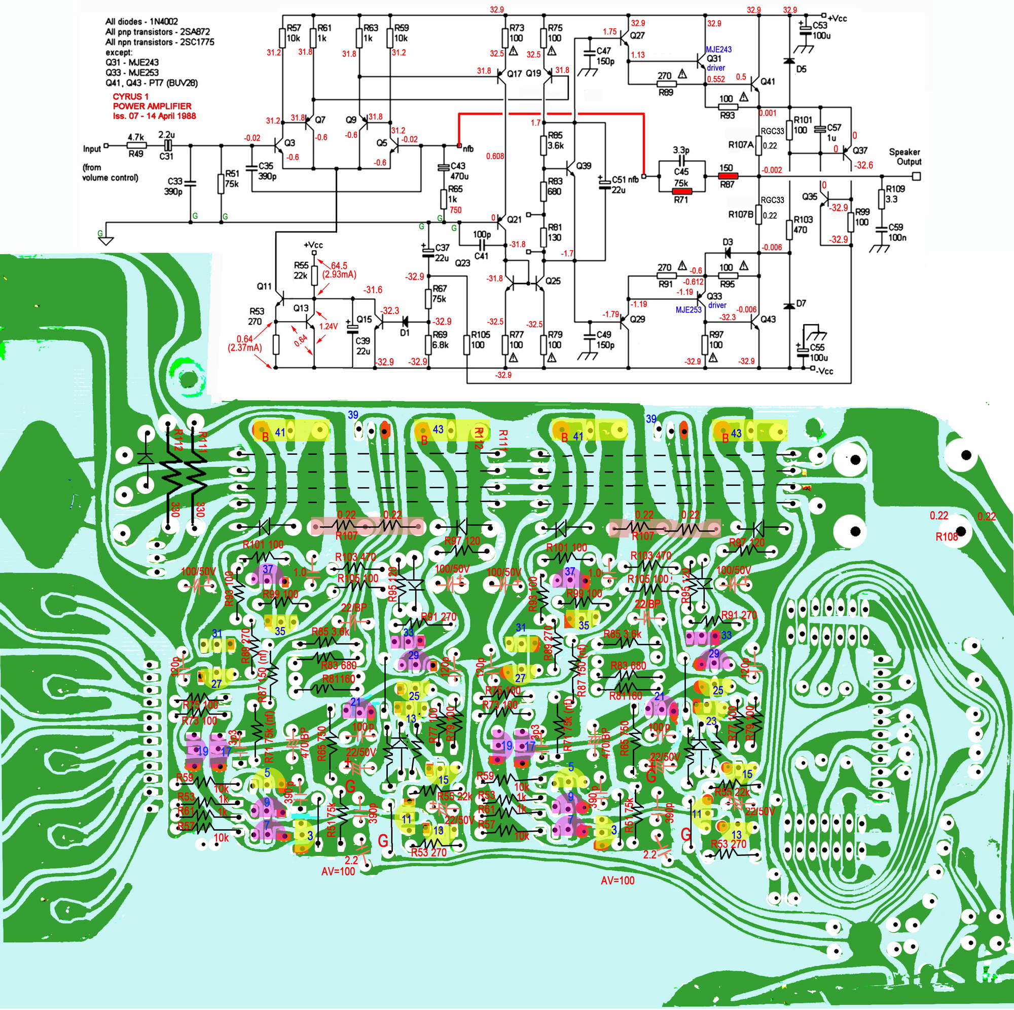
It is a bit difficult for you guys to repair it.
I have just repaired one and I took the time to redraw the PCB and measured the voltage to ease your job.
Sziasztok!
a fent említett autós cd került hozzám javításra végfok ic felrobbant mert a tulaj beleejtett egy vékony rézszálat és pont a végfok 5 lábát összezárta.a gyári ic PAL 012A ilyet nem kaptam csak állítólagos helyettesítőt amivel megszólalt csak kb 1 perc után kiírja AMP ERROR.
valaki tudja hol tudok ilyen ic beszerezni vagy valami tényleges helyettesítőt?
előre is köszönöm!
Üdv Attila
Hello,
Garantáltan nem lopott, 4 éves, újonnan vásárolt autóban a HYUNDAI EMP340 RDS MP3 USB CD LEJÁTSZÓ autórádió van.
Az okos szervíz akkut cserélt.
A kevésbé okos tulaj sehol nem találja a "security code" kártyáját.
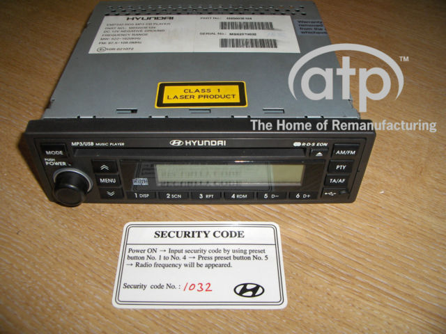 Így nézne ki.
Eldobhatóvá vált a kütyü, vagy van valami okosság?
Így nézne ki.
Eldobhatóvá vált a kütyü, vagy van valami okosság?
Így nézne ki.
Eldobhatóvá vált a kütyü, vagy van valami okosság?Similar manuals:

If you want to join us and get repairing help please sign in or sign up by completing a simple electrical test
or write your question to the Message board without registration.
You can write in English language into the forum (not only in Hungarian)!
or write your question to the Message board without registration.
You can write in English language into the forum (not only in Hungarian)!
E-Waste Reduce