Service manuals, schematics, eproms for electrical technicians
RADIOMARELLI UAL-UAL AM RADIO RECEIVER SCH

Type:  (PDF)
(PDF)
(PDF)Size
192.9 KB
192.9 KB
Page
1
1
Category
AUDIO
SERVICE MANUAL
AUDIO
SERVICE MANUAL
If you get stuck in repairing a defective appliance download this repair information for help. See below.
Good luck to the repair!
Please do not offer the downloaded file for sell only use it for personal usage!
Looking for similar radiomarelli manual?
Good luck to the repair!
Please do not offer the downloaded file for sell only use it for personal usage!
Looking for similar radiomarelli manual?
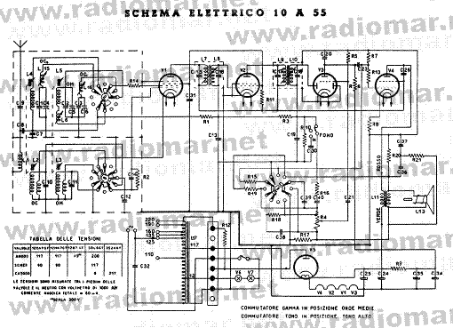
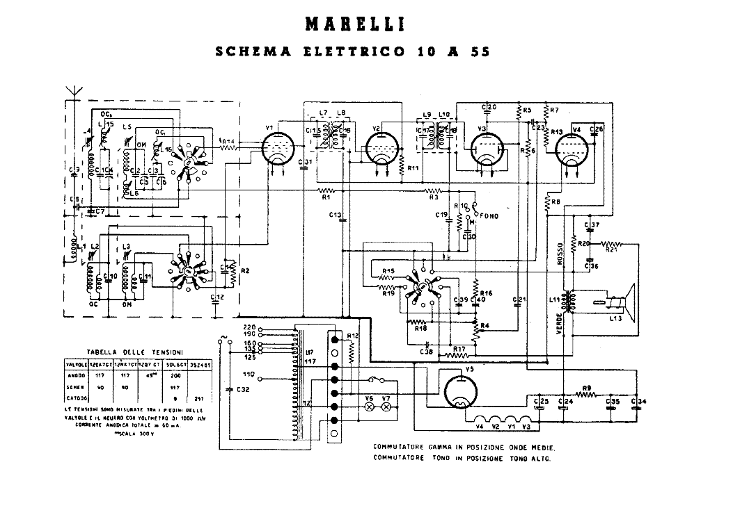
Document preview [1st page]

Click on the link for free download!
Advertisements
Please tick the box below to get download link:
- Also known:
UALUAL AM RADIO RECEIVER UAL UAL-UAL
- If you have any question about repairing write your question to the Message board. For this no need registration.
- If the site has helped you and you also want to help others, please Upload a manual, circuit diagram or eeprom that is not yet available on the site.
Have a nice Day! - See related repair forum topics below. May be help you to repair.
Warning!
If you are not familiar with electronics, do not attempt to repair!
You could suffer a fatal electrical shock! Instead, contact your nearest service center!
Note! To open downloaded files you need acrobat reader or similar pdf reader program. In addition,
some files are archived,If you are not familiar with electronics, do not attempt to repair!
You could suffer a fatal electrical shock! Instead, contact your nearest service center!
so you need WinZip or WinRar to open that files. Also some files are djvu so you need djvu viewer to open them.
These free programs can be found on this page: needed progs
If you use opera you have to disable opera turbo function to download file!
If you cannot download this file, try it with CHROME or FIREFOX browser.
Translate this page:
Relevant AUDIO forum topics:
Üdv urak!
Megint kukáztam egy jót reggel!
Találtam egy Orion SR 1025-ör recivert.
Meg kell mondjam megörültem neki, mert meglehetősen ritka darab már!
Apró üröm az örömben, hogy a készülék bár működik, táp, erősítő rész, am rádió rendben van, az FM állásban a forgókondit tekerve nem hangol a készülék!
Van esetleg valami tippetek? az SM-et ami itt fenn van letöltöttem!
Előre is köszi: Tibi
T. !
A készüléket megpróbáltam kitisztítani, a görgő, lendkerék csapágyazást zsírozni.
A lendkerék alsó csapágyát szétszedve a rugó kiugrott és nem tudom milyen
sorrendben kell kell visszaszerelni az alkatrészeket.
Ha valakinek lenne a csapágyról robbanttott ábra megköszönném.
A talált szervizkönyvekben csak az orsók szereléséhez van rajz.
Üdv.
gergosz0
Sziasztok!
Új vagyok itt és nem is szakmám,de kidobni nem akarom és értékben meg annyit nem ér,hogy utazzak vele valahová szerelőhöz.
Szóval van a fő panel és mellette az oldalához rögzítve egy kisebb panel van. Van rajta filter meg minden ami a hang útjába nem kellene ezért amikkel a főpanelhoz van kötve vezetékek abból nekem csak az rca jelre lenne szükségem ill. hogy sztereo módban működjön.
Két kérdés:Melyiken tudom direktbe bevinni a hangot tehát közvetlen az rca aljzatra forrasztva és hogy a híd kapcsolót ki kapcsoljam,tehát normál sztereóba tudjam használni.Se vágás semmi másra sincs szükségem belőle.
Az erő működik bár úgy látom javítva volt. Van egy susogós alapzaja is,de a kondi el volt folyva amit ki cseréltem,bár a rajzon nem találtam és én szerintem utólag lett bele rakva. Valószínűleg gerjedés miatt tették bele. A lényeg,hogy minden felesleges áramkört ki kötném belőle.
Ha tudnám,hogyan kell ide betölteni megtenném,de a kapcsolási rajz linkjét tudom csak beilleszteni
http://elektrotanya.com/the_harman_kardon_ca240.pdf/download.html
Sziasztok,
A címben említett erősítővel küzdök.
A tulaj szerint elejtette és azóta nem reagál semmire.
Én nagyobb sérülés nyomot még a külsején sem látok uh valójában nem tudom mi történ.
Jelenség:
Nem kapcsol be, készenlét sem világít, természetesen relék sem húznak.
Készenléti táp-nál a D117 egyenirányító híd kimenetén DC21,4V-ot mérek. Rajz szerint itt 6,8V-nak kellene lennie.
Ha valakinek van tapasztalata ezzel a berendezéssel, vagy hasonló jelenséggel azt megköszönném.
Üdv.:
Gyula
Similar manuals:


If you want to join us and get repairing help please sign in or sign up by completing a simple electrical test
or write your question to the Message board without registration.
You can write in English language into the forum (not only in Hungarian)!
or write your question to the Message board without registration.
You can write in English language into the forum (not only in Hungarian)!
E-Waste Reduce