Service manuals, schematics, eproms for electrical technicians
SONY D-SJ301 VER.1.2

Type:  (PDF)
(PDF)
(PDF)Size
1.3 MB
1.3 MB
Page
26
26
Category
AUDIO
SERVICE MANUAL
AUDIO
SERVICE MANUAL
If you get stuck in repairing a defective appliance download this repair information for help. See below.
Good luck to the repair!
Please do not offer the downloaded file for sell only use it for personal usage!
Looking for similar sony manual?
Good luck to the repair!
Please do not offer the downloaded file for sell only use it for personal usage!
Looking for similar sony manual?
Advertisements
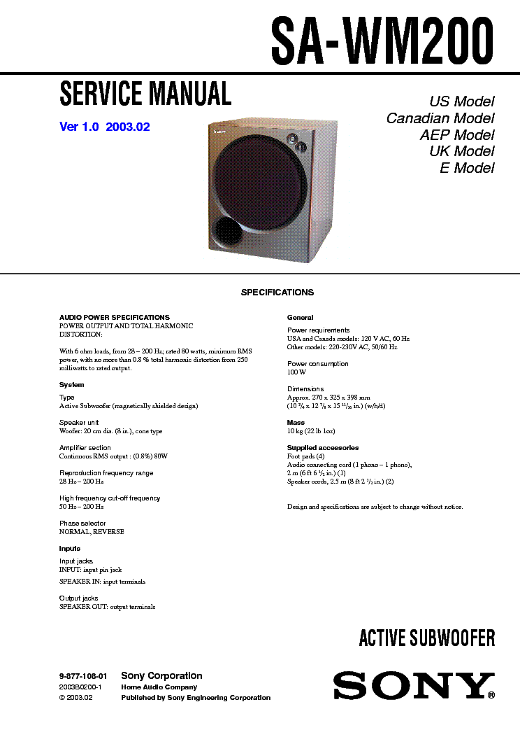
Document preview [1st page]

Click on the link for free download!
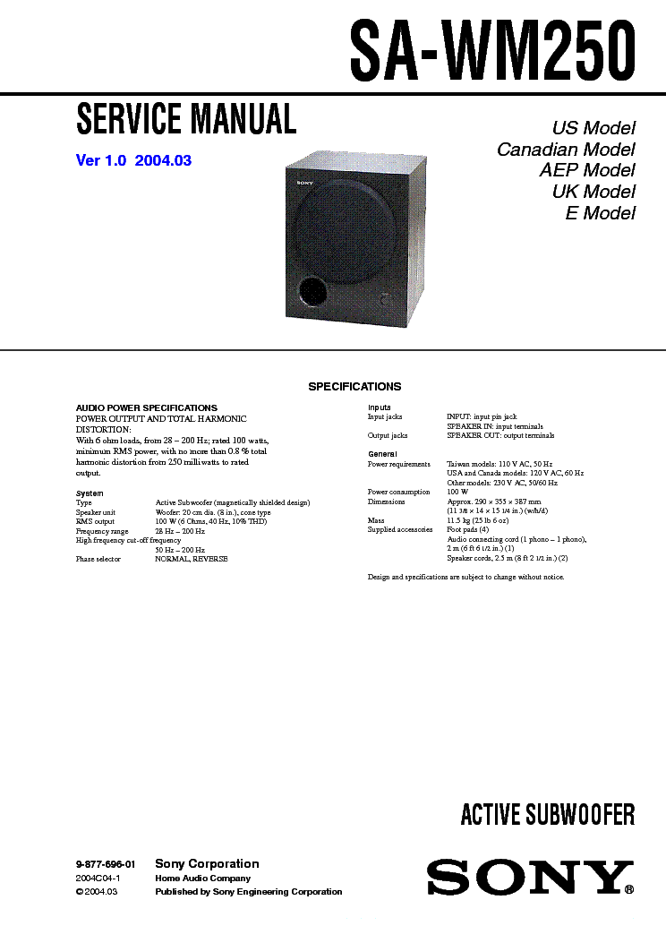
Document preview [2nd page]

Click on the link for free download!
Advertisements
Download free of charge (10 files / day):

Download processing...
Download processing...
- Also known:
SONY DSJ-301 DSJ301 DSJ 301 SJ301 D-SJ301
- If you have any question about repairing write your question to the Message board. For this no need registration.
- If the site has helped you and you also want to help others, please Upload a manual, circuit diagram or eeprom that is not yet available on the site.
Have a nice Day! - See related repair forum topics below. May be help you to repair.
Warning!
If you are not familiar with electronics, do not attempt to repair!
You could suffer a fatal electrical shock! Instead, contact your nearest service center!
Note! To open downloaded files you need acrobat reader or similar pdf reader program. In addition,
some files are archived,If you are not familiar with electronics, do not attempt to repair!
You could suffer a fatal electrical shock! Instead, contact your nearest service center!
so you need WinZip or WinRar to open that files. Also some files are djvu so you need djvu viewer to open them.
These free programs can be found on this page: needed progs
If you use opera you have to disable opera turbo function to download file!
If you cannot download this file, try it with CHROME or FIREFOX browser.
Translate this page:
Relevant AUDIO forum topics:
Sziasztok. Szuksegem van egy nehany tanacsra (vagy inkabb iskolaztatasra). Akar az "iskolapad" c. forumban is nyithattam volna a topikot, de 2 konkret radiorol van szo. Az egyik egy Sharp CD-C900 mini hifi. Automata keresovel nem talal egy adot sem, kezi keresessel szepen bejon mindegyik ado, megfelelo hangerovel. Ha megnyomom a sztereo gombot, azonnal eltunik a hang, ha mono-ra valtok ujbol visszajon a hang. AM mukodik rendesen, keresi, megtalalja es menti a memoriaba az adokat. Sajnos szervizkonyvet sehol a neten letoltheto formaban nem talaltam. Keszitettem fenykepeket a tuner panelrol. A masik keszulek egy Sony ST-D709 ami hasonlo jelenseget produkal, vagyis automata keresovel egyetlen adot sem talal, kezi keresessel bejonnek, de nagyon halkan. AM ezen is mukodik rendesen es sokkal hangosabb mint az fm. Ennek a manualja fenn van a tanyan, ennek a belsejerol is keszitettem kepeket. Elore is koszonom a segito szendeku tanacsokat. Udv.
Sziasztok!
Vettem egy Sony TC-FX210 magnót, ami szépen működik azt leszámítva, hogy a felvétel indításakor (szünet feloldásakor pontosabban) a bal oldalon -4, jobb oldalon -2 dB-ig folyamatosan világítani kezd a kivezérlésjelző. Mármint nem a zene hatására, hanem akkor is, ha még nem indult el a felvételi forrás, vagy letekerem a potmétert. Szalagtípustól függően ráadásul: a jobb oldal krómon már 0-ig, metálon +3-ig kitér! Így már egyáltalán nem is lehetne beállítani a helyes szintet..
Először azt hittem, valami gerjedés: javítottam már pár decket, amiben mechanikus átkapcsoló volt a felvételhez, és annak a kontakthibája produkált ilyen jelenséget (kimeneten hallható pattogással vagy sípolással egybekötve). De ebben nincs felvételi tolókapcsoló, elektronikusan vált üzemmódot. Sem a vonal kimeneten monitorozva, sem a fejhallgatóban nem jelenik meg semmi zaj a felvétel indításakor, sőt ha leszünetelve beállítom a kivezérlést (ekkor még normálisan jelez!), majd elindítom, egy kevés - gyanúsan fejkopásból eredő - magasveszteséget leszámítva tökéletes felvételt készít, semmi torzítás vagy gerjedés nincs!
Következő ötletem (a szalagtípus-függő szintből kiindulva): mi van, ha kijut az előmágnesező jel a kimenetre? Az nyilván nem hallható, mert nagyfrekvenciás, attól függetlenül az erősítőt még terheli, tehát nem túl egészséges jelenség. Viszont: kipróbáltam, hogy más deckek bemenetére rákötöttem ezt a Sony-t, és figyeltem a kijelzők együttfutását. Lejátszás közben szépen egymáshoz állítottam őket, de felvételkor már csak a Sony kijelzőjén ugrott meg a szint, a másikon nem történt semmi rendellenes. Aztán ütközésig feltekerve sem jeleztek semmit. És ez 3-4 készüléken ugyanúgy! Ezek után kicsit érthetetlen számomra, hogy a fejhallgató kimenetről meghajtott kivezérlésjelző hogyan tud hibázni...
A készüléket a napokban vásároltam, előélete ismeretlen. Hibásan vettem, hiányoztak róla a szíjak, amit persze már pótoltam. Megbontva látszólag nem volt még, nem hiányzik belőle semmi, és a fenti hibán kívül más rendellenességet nem vettem észre a működésében. A szervizkönyvet külföldi oldalról beszereztem, és feltöltöttem ide is.
A STDBY-LED a bekapcsolás kb. 3 mp után kialszik.A STDBY-LED-R bekapcsolás után a 0 V feszültség ugyan annyi idő alatt 3,3 V ra ugrik, akkor a Q623 RT1P441C-TP-1 led drive nem tud működni. Az EVER+3.3V és az EVER 4V mindig mérhető. A készülék szervíz kézikönyve elérhető a Fórum oldalain.
I found that VC1 0n IC11 is missing. After checking I found C25(330u 35V) s/c i.e. defect. The problem solved.
Want to share:
Have downloaded the schematics from this forum to help repair the amplifier of a friend.
Turned out that Sony decided to route the earth through the chassis, even the earth between the various supplies.
When one takes the main board out of the chassis and switches the amp on, there are up to 20 volts difference between the eart (and hence reference) of the pre-amps and the main amps.
Luckily the amp goes into protection but from a design point of view it is not nice to rely on screws and aluminum face plates to conduct up to 0.2 amps of current from one supply to another.
What I did is solder wires to every eart point and connected them on the main board to make it stand alone and not rely on conducting current through the chassis anymore.
Bad design, simple repair but took some digging in the schematics to find out what exactly was going on!
Similar manuals:


If you want to join us and get repairing help please sign in or sign up by completing a simple electrical test
or write your question to the Message board without registration.
You can write in English language into the forum (not only in Hungarian)!
or write your question to the Message board without registration.
You can write in English language into the forum (not only in Hungarian)!
E-Waste Reduce