Service manuals, schematics, eproms for electrical technicians
USSR C1-67 S1-67 OSCILLOSCOPE 1982 SM

Type:  (ZIP)
(ZIP)
(ZIP)Size
3.4 MB
3.4 MB
Page
---
---
Category
METER
SERVICE MANUAL
METER
SERVICE MANUAL
If you get stuck in repairing a defective appliance download this repair information for help. See below.
Good luck to the repair!
Please do not offer the downloaded file for sell only use it for personal usage!
Looking for similar ussr manual?
Good luck to the repair!
Please do not offer the downloaded file for sell only use it for personal usage!
Looking for similar ussr manual?
Document preview [1st page]

No preview item for this file.
Possible causes:
- No preview picture generated yet.
- It is not a pdf file.
Advertisements
Download free of charge (10 files / day):

Download processing...
Download processing...
- Also known:
USSR C-167 C167 S167 1982 167 C1 67 S1 C1-67 S1-67
- If you have any question about repairing write your question to the Message board. For this no need registration.
- If the site has helped you and you also want to help others, please Upload a manual, circuit diagram or eeprom that is not yet available on the site.
Have a nice Day! - See related repair forum topics below. May be help you to repair.
Warning!
If you are not familiar with electronics, do not attempt to repair!
You could suffer a fatal electrical shock! Instead, contact your nearest service center!
Note! To open downloaded files you need acrobat reader or similar pdf reader program. In addition,
some files are archived,If you are not familiar with electronics, do not attempt to repair!
You could suffer a fatal electrical shock! Instead, contact your nearest service center!
so you need WinZip or WinRar to open that files. Also some files are djvu so you need djvu viewer to open them.
These free programs can be found on this page: needed progs
If you use opera you have to disable opera turbo function to download file!
If you cannot download this file, try it with CHROME or FIREFOX browser.
Translate this page:
Relevant METER forum topics:
Sziasztok!
A címben nevezett labortápban nem gyújt az egyik tirisztor az egyenirányító hídban. Így félutas egyenirányítással csak 5-6A -ig terhelhető. Típusa SKT 24/04. Ez 24A és 400V-os. A kérdésem az lenne, hogy helyettesíthető-e Т10-20 у2 orosz tirisztorral, vagy T911-16-12 számomra ismeretlen gyártmányú tirisztorral? Illetve ezekhez a tirisztorokhoz keresek adatlapokat.
Előre is köszönöm a segítséget.
Üdv: Zoli
Sziasztok !
A sufniból előkerült egy retro ÉVÉ MINI műszer (Simon System) apró mechanikai hibával.Rajta vagyok az ügyön és ha meggyógyul ,jó lenne ismerni a használatát is. A gugli nem igazán barátom ,de ha valakinek lenne valami leírása ,kezelési utasítása ,szívesen venném a segítségét.
Köszönettel :
Józsi
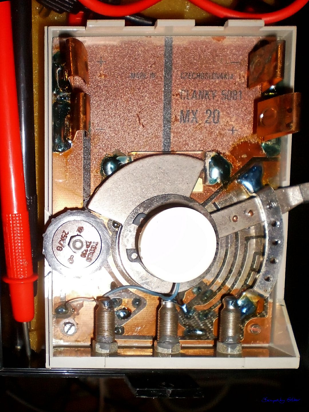
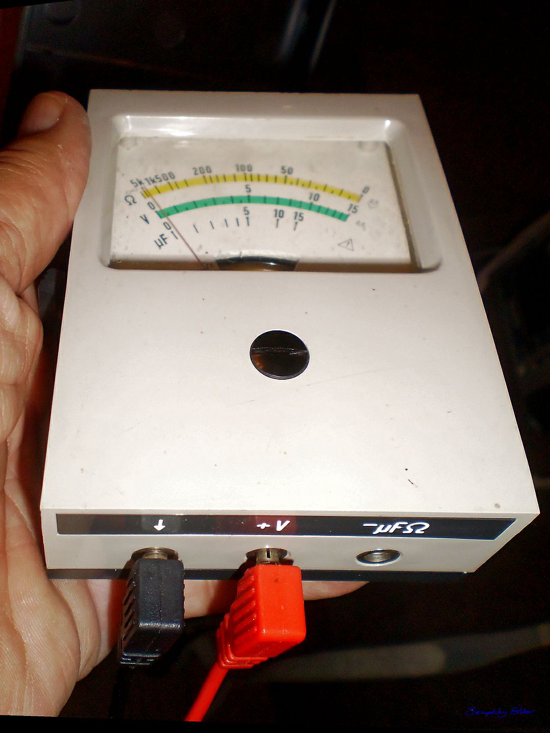
Hello Tanylakók!
A Clanky 5081 MX 20 Czechoslovakia kéziműszert ismeri-e valaki?
Mér:
Volt, Ohm, mikroFarad.
Hogyan mérhet elkókat?


Sziasztok!
Bedöglött a nem keveset látott de eddig remekül működő scopom. Nem ad képet. A képcső füt, elvileg az eltérítés is szabályoz, legalábbis a munkapontok, feszültség adatai változnak ha a helyzet potikat csavargatom. A nagyfesz trafó sokszorozó lábán érzékelhető nagyfesz. Esetleg ha valaki foglalkozik ilyen műszerek javításával annak a jelentkezését is várom.
Bedöglött a nem keveset látott de eddig remekül működő scopom. Nem ad képet. A képcső füt, elvileg az eltérítés is szabályoz, legalábbis a munkapontok, feszültség adatai változnak ha a helyzet potikat csavargatom. A nagyfesz trafó sokszorozó lábán érzékelhető nagyfesz. Esetleg ha valaki foglalkozik ilyen műszerek javításával annak a jelentkezését is várom.
Similar manuals:

If you want to join us and get repairing help please sign in or sign up by completing a simple electrical test
or write your question to the Message board without registration.
You can write in English language into the forum (not only in Hungarian)!
or write your question to the Message board without registration.
You can write in English language into the forum (not only in Hungarian)!
E-Waste Reduce