Service manuals, schematics, eproms for electrical technicians
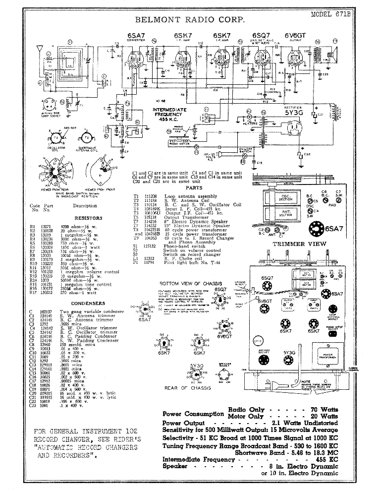
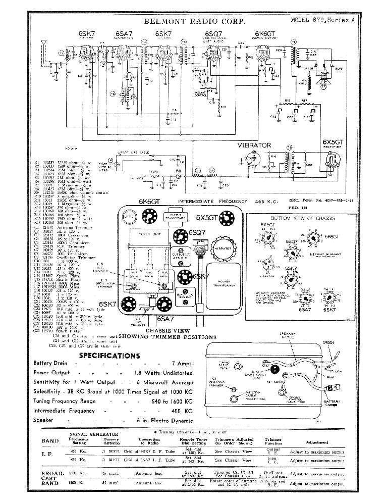
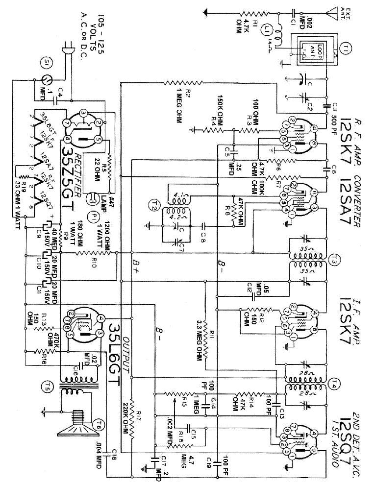
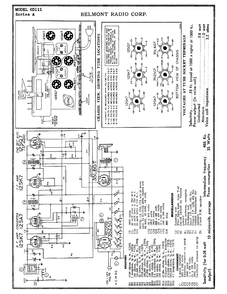
BELMONT 590 SM

AUDIO - SERVICE MANUAL
Type: (PDF)
Size
1.2 MB
Page
2
Category
AUDIO
SERVICE MANUAL
If you get stuck in repairing a defective appliance download this repair information for help. See below.
Good luck to the repair!

Please do not offer the downloaded file for sell only use it for personal usage!

Looking for similar belmont manual?
Advertisements
Document preview [1st page]
BELMONT 590 SM service manual (1st page)
Preview of BELMONT 590 SM [1st page]
Click on the link for free download!
Document preview [2nd page]
BELMONT 590 SM service manual (2nd page)
Preview of BELMONT 590 SM [2nd page]
Click on the link for free download!
Advertisements
Please tick the box below to get download link:
  • Also known:
    BELMONT 590
  • If you have any question about repairing write your question to the Message board. For this no need registration.
  • If the site has helped you and you also want to help others, please Upload a manual, circuit diagram or eeprom that is not yet available on the site.
    Have a nice Day!
  • See related repair forum topics below. May be help you to repair.
Warning!
If you are not familiar with electronics, do not attempt to repair!
You could suffer a fatal electrical shock! Instead, contact your nearest service center!

Note! To open downloaded files you need acrobat reader or similar pdf reader program. In addition, some files are archived,
so you need WinZip or WinRar to open that files. Also some files are djvu so you need djvu viewer to open them.
These free programs can be found on this page: needed progs
If you use opera you have to disable opera turbo function to download file!
If you cannot download this file, try it with CHROME or FIREFOX browser.
Translate this page:
Relevant AUDIO forum topics:
Fisher CA-M300 circuit diagram errors
Having downloaded the SM for the Fisher CA-M300 compact Stereo HiFi amp, realizing it is of good readable quality, I can spare myself to scan the SM and upload it, because it's exactly the same one as I have. Still I want to share a few thoughts having just repaired a set. I would like you (the admin) to put the following under the heading "Fisher CA-M300" in "Audio service info" The Fisher CA-M300 (built about 1981/82, for how long, I don't know, anyway, the company was then already owned by Sanyo) is a nice little, high quality built, very compact hifi stereo amp. I had the version built for Europe (220 V, 2 prong euro connector). Characteristics are: Sufficiently sized and shielded C-Core power transformer, huge (2 x 8000uF) electrolytic caps in the power supply, large extruded heatsink, bolted to big aluminium block, bolted to aluminium bottom plate, internal wiring between the different components and boards is well done, but, being of the wire-wrap type, rather unfriendly to the service (you have to disconnect 13 of them to get to the underside of the main circuit board, and you MUST _solder_ these when you put the equipment together again!). The circuitry is quite simple, using a Sanyo STK461 hybrid power IC in the output stage, a 4558 dual opamp in the tone control preamp, and 2 Hitachi Low-Noise HA1457 in the MM phono EQ preamp. There are 2 errors in the circuit diagrams: In the main circuit diagram the junction of R31 (33 Ohm) and R33 (220 Ohm / 1W) has to be connected to the positive rail - as it is in reality - otherwise the circuit could not work. In the STK461 equivalent circuit pin 12 has to be connected to the emitter of the right lower output transitor (the one opposite Q10, just like on the other side!), otherwise the circuit could not work. The fault reported by the owner was intermittent breaks in transmission and/or high distortion in mostly the left, but sometimes also in the right channel, both with loudspeaker and headphone output. This could sometimes be remedied by slapping on the housing, but mostly not. I at once suspected a mechanical connection fault, or a hairline break of the PCB. After taking off the top cover I could make the fault disappear/reappear by pressing with a finger on different parts of the main PCB. I now suspected the relay, which is a rather small encapsulated unit, but the clear plastic hood could be taken off, exposing the contacts and mechanism. Cleaning the contacts with blotting paper wetted with contact cleaner (1st effort) did not have a lasting effect. Same result using No. 600 abrasive paper (2nd effort). Not being able to find a suitable (or better) replacement of roughly that size, and after studying the circuit diagram, finding that no safety circuitry (DC on output detection or heat sensors) was found connected to the relay activating circuit, I decided to totally remove it, bridging the contacts. The function of the relay was just delayed connection of the output (ca. 1s) on switch on, and immediate disconnecting on switch off - to shield the user from the switch on/off noises (that are, in this special case, neither too nasty nor dangerous - a pure "comfort" function one could easily do without! To do the job, I had to dismantle the whole thing to get to the underside of the main PCB, I mentioned that above under the term "service unfriendly", but in the same time I think the makers should be forgiven, producing such a nice super compact design! The amp is working cleanly and clear again from now on... The amp being designed for 8 Ohm loads (in the European manual 4 Ohm is also specified) has been operating into 4 Ohm speakers (which are still quite usual here in Germany, and there are really god ones, too). If this is done at higher than usual power levels (of which the amp is quite capable), the high output currents may have damaged the relay contacts in the long run. The contacts must clearly be declared "under designed" for this kind of duty. By the way, as you can see from the circuit diagram, when both sets of stereo speakers are connected, and you run them both, they are connected in series, so there is no danger of overload, but the sound will of course be not as good (because of the lower damping and the impedance interference of the serial connection, you can hear that). Some additional thoughts about relays in the output lines of hifi amps: Now I'm all in favor of speaker protection in the case of DC appearing on the output. The CA-M300 depends on 1.6AT (slow blow) fuses in the output lines, which would amount to 20W RMS into 8 Ohm. But fuses are bad in the output lines, they will bring distortion having a nonlinear resistance (and if they had none, how could the ever blow?). Have you ever seen a fuse wire sagging under heavy load? Relay contacts are bad, too. They should be extra heavy duty, and the relays made pluggable for ease of service and, yes, those contacts _will_ wear out, so the relays will have to be replaced. Having relays for delayed switch on / immediate switch off in the output of preamps with their very low current requirements seems OK (the contacts being of good quality, of course), but having relays in the output line of power amps just to avoid switch on/off noises seems just a superfluous nuisance... To point you to some more modern ideas for perhaps new designs of output protection avoiding relays I recommend the following web article: http://www.geofex.com/Article_Folders/ampprot/dcprot.htm Back to the CA-M300, if the output stage should be faulty, even one channel only, the Hybrid IC STK461 has to be replaced in total. I would recommend replacing it with the STK465, which is rated for higher voltage, because the the STK461 is running very near its maximum rating with a 230 V AC line (and at my home it's mostly 236 V AC), provided you can get these devices which are not in production anymore. Otherwise the power PCB has to be discarded and something new constructed instead, perhaps something using the ST TDA7295 or the NatSemi LM3886 from the overture series. Space would be there (even considering a Veroboard design) and sufficient heatsinking, too!
SONY MEX-DV1000 cd Eject problem
Sziasztok! Sony MEX-DV1000 autó rádióm van. A cd-ket beolvassa és szól is. A probléma az amikor megnyomom az EJECT gombot a cd-t nem akarja kidobni. Próbáltam visszahajtani a cd mehanizmusát (tehát kivettem a cd-t) és azután belerakni a cd-t. Szépen behúzta a cd-t felismerte, de nem akarta kidobni. Tehát a cd LOADING műkszik az EJECTING pedig nem. Előre is köszonöm. Sikerült medjavitani a rádiót. A baj zéner diódában volt, a door sw-re. Nem a kapcsolónál hanem a proc. bemeneténél. Igy hát a proc. úgy ismerte fel hogy az elölap nincsen lenyitva, és akkor nem dobja ki a cd-t. Most a led diódák is dolgoznak. Kössz mindenkinek a segitséget.
Castone CT-700 gerjed, instabil
Sziasztok! Ma került hozzám egy Castone CT-700-as végfok,az egyik oldala tökéletes a másik viszont lekapcsolgat,a kimenetre mérve kiderült hogy az egyen fesz szaladgál ide oda,ez még nem is lenne nagy probléma más végfokoknál is volt ilyen általában zárlatos vagy kifogyott kondi vagy belső kontakt hibás tranzisztor okozza.A panelhibát kizártam,bemeneti ic-t megcseréltem a jó oldallal azzal sincs baj,viszont mostanra kiderült,hogy ha a bemeneti ic lábait megfogom akkor egészen a fél tápfeszig(80volt) van a kimenet és majd lassan visszamegy pár voltra,a jó oldalon ugyanez a beavatkozás semmi problémát nem okoz.Ezt már kínomban próbálgattam mert semmi ötletem nincs hogy mi lehet a baj,egyébként ha a kimenetet egy kondival leválasztom ugyanúgy szól az erősítő,persze csak halkan próbáltam.Megköszönném ha valakinek lenne valami használható ötlete a problémára! Előre is köszi! "FONTOS! Olyan fórum téma nevet válassz, ami beszédes, minél pontosabban illeszkedik arra, amivel kapcsolatban írsz. Egy lehetséges jó elnevezés pl: ORION LCD PT26S chassis 17MB12-2, a tápja nem indul Az nem elég, hogy pl: "LG LCD-TV" vagy "HP laptop" és hasonlóak. Illetve érdektelen, nem releváns információt se tartalmazzon a cím! A helytelenül elnevezett topik felfüggesztésre, majd 48 óra után törlésre kerül! Felfüggesztett állapotban nem tudnak mások addig hozzászólni, amíg ki nem javítod a címet. A hibás cím utólagos javítása (48 órán belül) a "Szerkesztés" fülre kattintva végezhető el"
Sony HCD-RXD9 "specialistát" keresek: Sűrűn meghibásodik az STK 411-230E
Sziasztok! Egy Sony HCD-RXD-9 HI-FI-vel szenvedek. Valamikor télen cseréltem STK-t benne, ami most májusban ismét elszállt (legalábbis az egyik fele.) Megrendeltem, kicseréltem, remekül működött, ráadásul én 4ohmos hangfallal próbáltam. Hazavitték,és már másnap szóltak, hogy az első bekapcsoláskor megint "protect". Persze, megint az STK, és mindkét fele. Megint megrendeltem, de mielőtt kicseréltem volna, betettem az előzőt, és az (az egyik fele) most is remekül működik. Bekértem a hangfalakat is, azok hibátlanok, a vezetékek is sértetlenek. Ami gyanús, és nem világos, a következő: A SM-ban a rajzon az szerepel, hogy a HV+ és - az +-50V, az LV+ és - pedig +-29V. A készülékben mindkét esetben +-50V-okat mérek. A +-29V ok egy graetz-ről, és a két elkóról jönnek, semmi más nincs a körben egészen az IC-ig. Ami szintén gyanús, az, hogy a HV tápokon két 71V-os elkó van (ez rendben is volna), de az LV tápokon 50V-os elkók vannak. Tudomásom szerint, ha ott is 50V-nak kellene lennie, akkor az elkóknak is nagyobb feszültségűeknek kellene lennie, kissé többnek, mint a mérhető, névleges feszültségnek. Az elkók jók! Tudja valaki, hogy mit kellene mérnem? Vagy mit nem vettem figyelembe? Arra még gondolni sem merek, hogy az IC-k hibásak, hiszen "bemérve, kipróbálva" adták el (:)) Köszönettel: Attila
Similar manuals:
If you want to join us and get repairing help please sign in or sign up by completing a simple electrical test
or write your question to the Message board without registration.
You can write in English language into the forum (not only in Hungarian)!

E-Waste Reduce