Service manuals, schematics, eproms for electrical technicians
CONTINENTAL RADIO-TELEVISION CORP. 6Q SCH

Type:  (PDF)
(PDF)
(PDF)Size
46.8 KB
46.8 KB
Page
2
2
Category
AUDIO
SERVICE MANUAL
AUDIO
SERVICE MANUAL
If you get stuck in repairing a defective appliance download this repair information for help. See below.
Good luck to the repair!
Please do not offer the downloaded file for sell only use it for personal usage!
Looking for similar continental manual?
Good luck to the repair!
Please do not offer the downloaded file for sell only use it for personal usage!
Looking for similar continental manual?
Advertisements
Document preview [1st page]

Click on the link for free download!
Document preview [2nd page]

Click on the link for free download!
Advertisements
Please tick the box below to get download link:
- Also known:
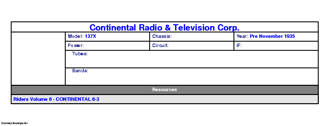
CORP. 6Q RADIO TELEVISION
- If you have any question about repairing write your question to the Message board. For this no need registration.
- If the site has helped you and you also want to help others, please Upload a manual, circuit diagram or eeprom that is not yet available on the site.
Have a nice Day! - See related repair forum topics below. May be help you to repair.
Warning!
If you are not familiar with electronics, do not attempt to repair!
You could suffer a fatal electrical shock! Instead, contact your nearest service center!
Note! To open downloaded files you need acrobat reader or similar pdf reader program. In addition,
some files are archived,If you are not familiar with electronics, do not attempt to repair!
You could suffer a fatal electrical shock! Instead, contact your nearest service center!
so you need WinZip or WinRar to open that files. Also some files are djvu so you need djvu viewer to open them.
These free programs can be found on this page: needed progs
If you use opera you have to disable opera turbo function to download file!
If you cannot download this file, try it with CHROME or FIREFOX browser.
Translate this page:
Relevant AUDIO forum topics:
Sziasztok!
Tudnátok segíteni?
Hoztak egy ilyet. Típus nincs rajta.
Csatornánként 8 egyforma végtranyo van benne. 4 az alaplapon, és 4 egy segédpanelon, ami a forrasztási oldalukkal össze van fordítva, még hozzá férni se lehet. Az egyik fele jó, ebbe 8*KD503, a másik kimenetén +29V van ebben 8* 2N3773 van. +-70 voltról megy, ami megvan. A bemenetén A NE5534P van. A rossz oldal NE5534P kimenetén (6 pin) a +14V mérek :( A IC +-14V tápja megvan. Ha leválasztom a élőfokot akkor is 14V mérek az IC kimenetén, de a meghajtó tranyok bázisa felé is 14V körüli fesz megy ilyenkor is, sőt ha kiveszem az IC-t akkor is . Itt megakadtam.
Sok rajzot megnéztem, de egyik se az. Nincs meg Valakinek a ez a rajz?
Köszi
Üdvözlet Mindenkinek!
Ez a leges legelső topikom.
Végső megoldásként fordulok hozzátok a problémámmal:
Sikerült hozzájutnom a fent nevezett magnóhoz, viszont amint levettem a hátlapját vált láthatóvá a nem kis gond! Két hangszóró rákötve a jobb végfok IC-re, a bal végfok IC-nek hűlt helye, és ami legrosszabb a környékén a panel szét égve. IC-m még lenne, de a felégett panellal sajnos nem tudok mit kezdeni. Varázsló nem vagyok.
Röviden: Nagy szükségem lenne a kapcsolási rajzára! Tudom hogy fizetősen lehet vásárolni a neten, de ilyet még nem csináltam. Ha esetleg valaki már vásárolt így, és ezt is meg tudná szerezni, annak kifizetem a költségét!
Köszönettel: Mátyás
Üdv.
Sikerült megszereznem az SM-et, fel akartam tölteni ide, de 60 mega és nem engedi.
Mi ilyenkor a teendő?
Attila
Want to share:
Have downloaded the schematics from this forum to help repair the amplifier of a friend.
Turned out that Sony decided to route the earth through the chassis, even the earth between the various supplies.
When one takes the main board out of the chassis and switches the amp on, there are up to 20 volts difference between the eart (and hence reference) of the pre-amps and the main amps.
Luckily the amp goes into protection but from a design point of view it is not nice to rely on screws and aluminum face plates to conduct up to 0.2 amps of current from one supply to another.
What I did is solder wires to every eart point and connected them on the main board to make it stand alone and not rely on conducting current through the chassis anymore.
Bad design, simple repair but took some digging in the schematics to find out what exactly was going on!
Similar manuals:
If you want to join us and get repairing help please sign in or sign up by completing a simple electrical test
or write your question to the Message board without registration.
You can write in English language into the forum (not only in Hungarian)!
or write your question to the Message board without registration.
You can write in English language into the forum (not only in Hungarian)!
E-Waste Reduce