Service manuals, schematics, eproms for electrical technicians
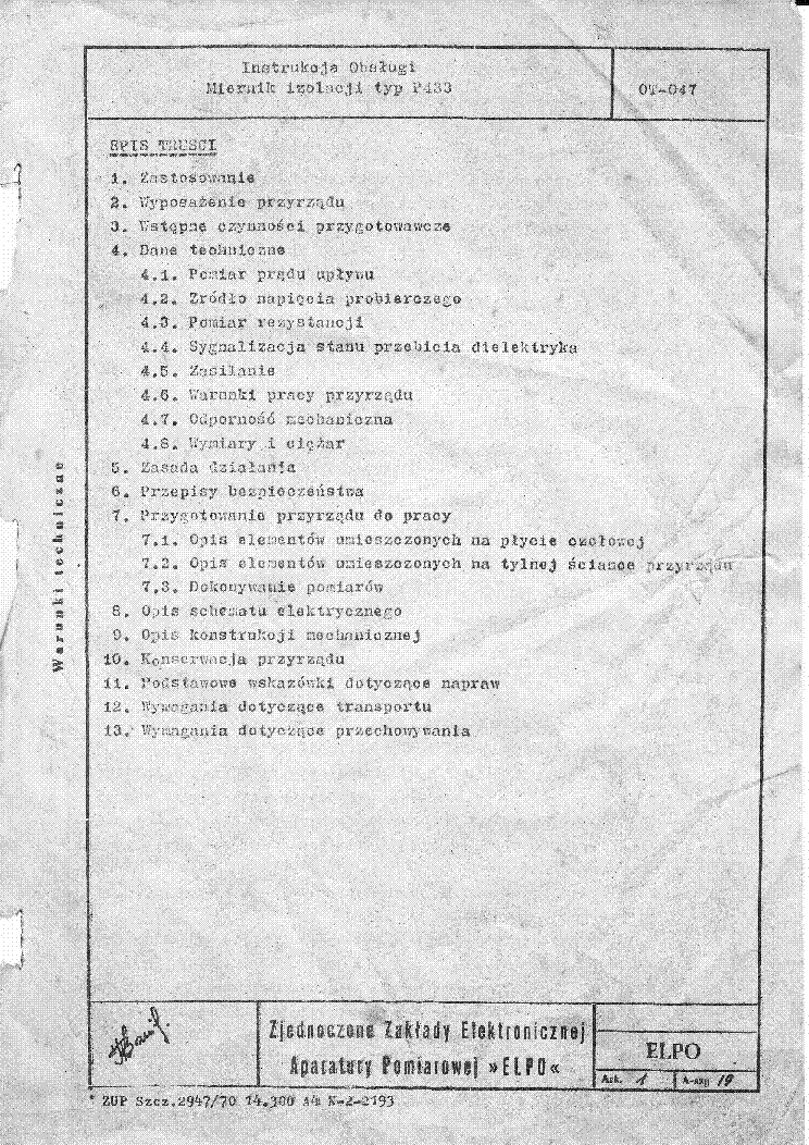
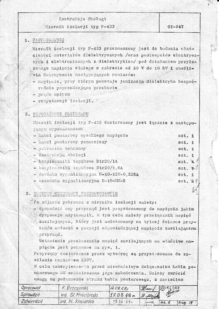
ELPO P433 ISOLATION METER SM

Type:  (PDF)
(PDF)
Size
15.4 MB
15.4 MB
Page
20
20
Category
METER
SERVICE MANUAL
METER
SERVICE MANUAL
If you get stuck in repairing a defective appliance download this repair information for help. See below.
Good luck to the repair!
Please do not offer the downloaded file for sell only use it for personal usage!
Looking for similar elpo manual?
Good luck to the repair!
Please do not offer the downloaded file for sell only use it for personal usage!
Looking for similar elpo manual?
Advertisements
Advertisements
Please tick the box below to get download link:
- Also known:
ELPO P-433 METER P433 ISOLATION 433
- If you have any question about repairing write your question to the Message board. For this no need registration.
- If the site has helped you and you also want to help others, please Upload a manual, circuit diagram or eeprom that is not yet available on the site.
Have a nice Day! - See related repair forum topics below. May be help you to repair.
Warning!
If you are not familiar with electronics, do not attempt to repair!
You could suffer a fatal electrical shock! Instead, contact your nearest service center!
Note! To open downloaded files you need acrobat reader or similar pdf reader program. In addition,
some files are archived,If you are not familiar with electronics, do not attempt to repair!
You could suffer a fatal electrical shock! Instead, contact your nearest service center!
so you need WinZip or WinRar to open that files. Also some files are djvu so you need djvu viewer to open them.
These free programs can be found on this page: needed progs
If you use opera you have to disable opera turbo function to download file!
If you cannot download this file, try it with CHROME or FIREFOX browser.
Translate this page:
Relevant METER forum topics:
Sziasztok!
14 évvel ezelőtt tulajdonomba került Fluke 189 multiméter pontosságát szeretném ellenőriztetni, ahogy a szakik mondják „kalibrálni” nem „horribilis” áron. Egy pár kalibrálással és hitelesítéssel foglalkozó kft/bt megkeresése során kicsit elment a kedvem a több 10 ezres nettó árajánlatoktól. Ritkán, de előfordul, hogy elég nagy pontosságú műszereket kell beállítsak és már nem merem bevállalni, felhasználói kézi könyvében évi egyszeres kalibrálás van előírva, nahát ez egyszer meg is történt amikor lekerült a gyártó sorról. Ahogy a hasonló jellegű hozzászólásokban is olvastam talán van valakinek ennél több digites mérőműszere összehasonlítás céljából.
Üdv
Sziasztok!
A címben jelzett regenerálómban elfüstölt a BU208 és még egy ellenállás.
Ha valaki tudja, hogy a BU 208 áramkörében látható két nagyobb teljesítményű ellenállásból a 12KOhm-os elenállással párhuzamos ellenállásnak mi a pontos értéke, annak fizetnék egy sört. Na jó, kettőt is:-).
BMR80-as rajzom van, de sajnos nem egyezik a két áramkör.
Képet mellékelek...
A képen látható világos négyzet a kérdéses ellenállás helye.
Előre is köszi!
dongo
Sziasztok!
Hozzám került egy békebeli digitális multiméter, elég kevés info van róla a neten, GDM 392 névre hallgat. Klasszikus forgató üzemmód kapcsoló és pár funkció gomb(Min/Max.Hold. Rel.) köztük "Reset" is. Ezt megnyomva újraindul a műszer. Korához képest teszi is a dolgát, azonban amit kifogásolni lehet rajta , egy olyan jelenség amit még egyetlen multiméternél sem tapasztaltam. Ha egy olyan elosztóba mérem a 230 AC-t amibe más fogyasztó is van, példaként egy labortáp volt (nem kapcsoló üzemű) és azt ki/be kapcsolgatom akkor "reset" van a műszeren, újraindul és méri tovább a 230-at. 10 kapcsolásból 8x újra indult ( mintha a 'Reset" gombot nyomtam volna) de volt eset hogy eltűnt a kijelzés teljesen és csak egy újbóli kapcsolásnál jelent meg. NJU9210 a lelke.
Mi okozhatja ezt a jelenséget ?
Üdv
Malibu
Helló ! Szereztem egy műszeralkatrészt, aminek a beazonosításában kérek segítséget. Az alkatrész egy kijelző panel, rajta 3 db TIL akármilyen kijelzővel (szerintem TIL306-307-308-309 valamelyike lehet), és az egyes kijelzőkhöz tartozó 7475-74192 számláló-tároló kombóval. Ez a panel valami frekvenciamérést, impulzus mérést vagy számlálást csinálhatott, de eddig nem találkoztam sem EMG, sem más ismertebb magyar gyártó által elkövetett olyan műszerrel, amibe esetleg bekerülhetett ez a panel (ugyanis, legalább 3,5 digitesnek kéne lenni ahhoz).
Ha bárki tud valami okosat mondani az alkatrészre vonatkozólag, esetleg valami rajzot is tud hozzá, azt nagyon megköszönöm.
Similar manuals:
If you want to join us and get repairing help please sign in or sign up by completing a simple electrical test
or write your question to the Message board without registration.
You can write in English language into the forum (not only in Hungarian)!
or write your question to the Message board without registration.
You can write in English language into the forum (not only in Hungarian)!
E-Waste Reduce


