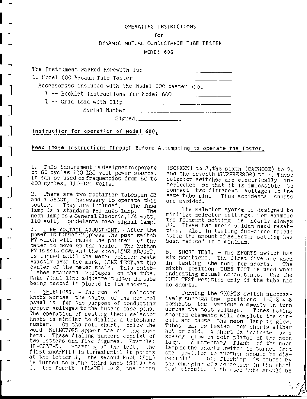
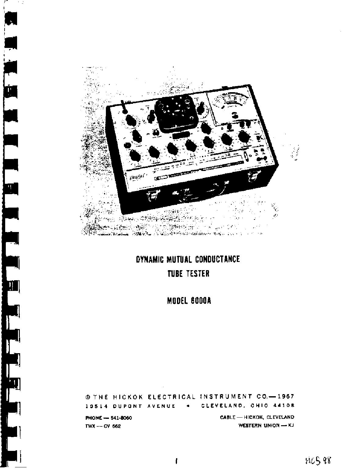
HICKOK CARDMATIC TUBE TESTER KS-15874-L2.

1.4 MB
73
METER
SERVICE MANUAL
Good luck to the repair!
Please do not offer the downloaded file for sell only use it for personal usage!
Looking for similar hickok manual?

No preview item for this file.
Possible causes:
- No preview picture generated yet.
- It is not a pdf file.
- Also known:
HICKOK CARDMATIC TUBE TESTER KS15874L2. KS 15874 L2.
- If you have any question about repairing write your question to the Message board. For this no need registration.
- If the site has helped you and you also want to help others, please Upload a manual, circuit diagram or eeprom that is not yet available on the site.
Have a nice Day! - See related repair forum topics below. May be help you to repair.
If you are not familiar with electronics, do not attempt to repair!
You could suffer a fatal electrical shock! Instead, contact your nearest service center!
so you need WinZip or WinRar to open that files. Also some files are djvu so you need djvu viewer to open them.
These free programs can be found on this page: needed progs
If you use opera you have to disable opera turbo function to download file!
If you cannot download this file, try it with CHROME or FIREFOX browser.
Hozzáértő szakit keresek, vagy tanácsot kérnék:
A Hameg Hm 507 szkópom úgy tűnik, meghibásodott. Az egyik hiba, hogy azY1 csatorna a másikhoz képest sokkal érzéketlenebb. A másik, hogy a csatolt képen a felső harmadban furcsa, pontokból álló sáv látható. Sajnos, nem ismerem a készüléket belülről, ezért kérnék tanácsot, vagy keresek hozzáértő kollégát. (Lehetséges, hogy invertermérés közben hibásodott meg, nem emlékszem.)
Köszönettel:
Attila
Tisztelt kollégák!
Ezzel a műszerrel (is) lettek a HIKI-ben gyártott multiméterek hitelesítve. 10mV-tól 1000V-ig ad ki egyenfeszültséget,
1-3-10 stb. lépésekben. A 70-es évek közepén készült, és ez az egy darab létezik belőle. 100V-ig van duplázógomb, polaritást lehet váltani, valamint folytonos szabályozás is lehetséges.
Az alsó kapcsolósor egymást kiváltó gombjai elkoptak, a gombok nem maradtak benn. Sok idő telt el, míg találtam ilyen ISOSTAT gombokat. A kapcsolósor nem nyákban van, hanem behuzalozva lebeg, ezért fényképeket csináltam, hogy vissza tudjam majd szerelni. Sajnos nem sikerült elég jól mindent lefényképezni, ezért kénytelen voltam az egész készülék teljes kapcsolási rajzát felvenni, hogy a homályos dolgokra fényt derítsek.
A precíziós ellenállások ma is teljesen pontosak, gondolom anno válogatva lettek. Az erősítők a HIKI-ben akkor divatos kiskártyák (uA741, uA725). A kályha egy későbbi felújításkor került bele.
Korábban a (kb 10 éve) táptrafót át kellett tekertetnem, mert nagyon nagy volt a nyugalmi árama.
Kapott egy új díszelőlapot is.
Most kifogástalanul működik, és pontos, mert semmilyen potmétert nem tekertem el.
üdv
bbgames
Kéréssel fordulnék szakavatott EMG műszerekben járatos taghoz!
Fent nevezett szkóp kapcsolási rajzom van ,de feszültség adat sehol a rajzon!
Szóval olyan szakit keresnék aki tud is feszültség értékekkel szolgálni még jobb ha anódáram értéket is tud,vagy esetleg a trafók gyári méretezéséről van doksia!
1db trafót kéne tekerni ,sajnos adatok hiányában nehéz elindulni !
Köszönöm
Zoli
21:03Válaszd ki a megfelelő fórumot, majd adj neki címet és írd be a kérdésed.
A téma címe tartalmazza a hibás eszköz márkáját és típusát. Szintén tartalmazza röviden a problémát.
pl: ACER AL1711 monitor képernyője 5 másodperc után kikapcsol
A helytelenül elnevezett topik felfüggesztésre, majd 48 óra után törlésre kerül! Felfüggesztett állapotban nem tudnak mások addig hozzászólni, amíg ki nem javítod a címet!
A hibás cím utólagos javítása (48 órán belül) a "Szerkesztés" fülre kattintva végezhető el.
Rajzot, service manualt, jobbra a "Keresem/WANTED" doboz "KATT IDE" gombján keresztül kérj!
or write your question to the Message board without registration.
You can write in English language into the forum (not only in Hungarian)!


