Service manuals, schematics, eproms for electrical technicians
PHILIPS 10CX1120 SERVICE-INFO

Type:  (PDF)
(PDF)
(PDF)Size
424.6 KB
424.6 KB
Page
3
3
Category
TV
INFO-TIPS
TV
INFO-TIPS
If you get stuck in repairing a defective appliance download this repair information for help. See below.
Good luck to the repair!
Please do not offer the downloaded file for sell only use it for personal usage!
Looking for similar philips manual?
Good luck to the repair!
Please do not offer the downloaded file for sell only use it for personal usage!
Looking for similar philips manual?
Advertisements
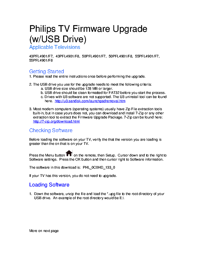
Document preview [1st page]

Click on the link for free download!
Document preview [2nd page]

Click on the link for free download!
Advertisements
Download free of charge (10 files / day):

Download processing...
Download processing...
- Also known:
PHILIPS 10CX1120 10 CX 1120 INFO
- If you have any question about repairing write your question to the Message board. For this no need registration.
- If the site has helped you and you also want to help others, please Upload a manual, circuit diagram or eeprom that is not yet available on the site.
Have a nice Day! - See related repair forum topics below. May be help you to repair.
Warning!
If you are not familiar with electronics, do not attempt to repair!
You could suffer a fatal electrical shock! Instead, contact your nearest service center!
Note! To open downloaded files you need acrobat reader or similar pdf reader program. In addition,
some files are archived,If you are not familiar with electronics, do not attempt to repair!
You could suffer a fatal electrical shock! Instead, contact your nearest service center!
so you need WinZip or WinRar to open that files. Also some files are djvu so you need djvu viewer to open them.
These free programs can be found on this page: needed progs
If you use opera you have to disable opera turbo function to download file!
If you cannot download this file, try it with CHROME or FIREFOX browser.
Translate this page:
Relevant TV forum topics:
Szevasztok !!!
utcán talált TV távirda nélkül, A66EAK071, gyerekzár van rajta, hogyan lehetne Resetelni valahogy ? Köszönet előre is ha választ kapok !!!
utcán talált TV távirda nélkül, A66EAK071, gyerekzár van rajta, hogyan lehetne Resetelni valahogy ? Köszönet előre is ha választ kapok !!!
Sziasztok
Ismét sikerült beletenyerelni a jóba. Eme gépet több kolléga sikertelen küzdelme után hozták. Készenlét van, indításkor hallani a függő vég kerregését, a nagyfeszt nem. Viszont van egy pillanatra mert a csüvet feltölti. El viszont nem indul, egy pillanatra sem alszik ki a stanby led. Kondik cserélve lettek, FBT-is utángyártott Kínai. CT6538 ez minden ami olvasható, hacsak az alján nincs valami. A tápmodult is cseréltem, ugyan azt csinálja. Ja, a tápja jónak tűnik 75w-s izzóval. Lehet trafó? mostaság az összes philipsem trafóhibás volt, igaz nem mai darabok, ez sem. Ha valaki tudna valami bíztatót örülnék neki. Köszönöm.
Sziasztok!
Azzal maradt itt, h. csőhibás.
Gondoltam ma ránézek. Egyfókuszos philips cső, ezek nem szoktak beszarni.
Mérve tökéletes, bekapcsolva sincs csőtünet.
Kép felső harmadában egy vizszintes fehér csík, ami kb. 10-10 centire befelé van, tehát nincs egész végig vagy mi :) Eztán letilt és kikapcs.
5let esetleg?
Akkora dög, gyorsban le kéne takarítanom :)
Most nézek bele egy eltérítő IC-t, nekem gyanús kicsit.
Üdv:
Pityesz
Szép napot mindenkinek.Ismét egy akadály egy Philips 17ht3352/412 tv esetében.Hotel modban van,mert csak a hangerö és a programváltás müködik.A proci helyén csatlakozó,amely kivezetődik egy másik panelra,ahol megtalálható egy P80C652 proci,hozzá eeprom és teletext(SAA5281P).Ezen a panelon van egy csatlakozó,ami a készülék hátuljára van kivezetve egy párhuzamos port(Dsub25) tipusu csatlakozó.Még ráadásul egy tuner is van a panelon antenna ki-be lehetöséggel.Persze az alaplapon van saját tunerje a tvnek.Mit tegyek???
Similar manuals:


If you want to join us and get repairing help please sign in or sign up by completing a simple electrical test
or write your question to the Message board without registration.
You can write in English language into the forum (not only in Hungarian)!
or write your question to the Message board without registration.
You can write in English language into the forum (not only in Hungarian)!
E-Waste Reduce