Service manuals, schematics, eproms for electrical technicians
PREMIER RTR-600Z CHASSIS JV-565-LA02,JV-565-88LA SCH

Type:  (RAR)
(RAR)
(RAR)Size
949.3 KB
949.3 KB
Page
---
---
Category
TV
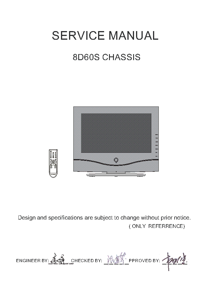
SERVICE MANUAL
TV
SERVICE MANUAL
If you get stuck in repairing a defective appliance download this repair information for help. See below.
Good luck to the repair!
Please do not offer the downloaded file for sell only use it for personal usage!
Looking for similar premier manual?
Good luck to the repair!
Please do not offer the downloaded file for sell only use it for personal usage!
Looking for similar premier manual?
Document preview [1st page]

No preview item for this file.
Possible causes:
- No preview picture generated yet.
- It is not a pdf file.
Advertisements
Please tick the box below to get download link:
- Also known:
PREMIER RTR-600Z CHASSIS RTR600Z JV565LA02 JV56588LA RTR 600 JV 565 LA 02 56588 600Z LA02 88LA
- If you have any question about repairing write your question to the Message board. For this no need registration.
- If the site has helped you and you also want to help others, please Upload a manual, circuit diagram or eeprom that is not yet available on the site.
Have a nice Day! - See related repair forum topics below. May be help you to repair.
Warning!
If you are not familiar with electronics, do not attempt to repair!
You could suffer a fatal electrical shock! Instead, contact your nearest service center!
Note! To open downloaded files you need acrobat reader or similar pdf reader program. In addition,
some files are archived,If you are not familiar with electronics, do not attempt to repair!
You could suffer a fatal electrical shock! Instead, contact your nearest service center!
so you need WinZip or WinRar to open that files. Also some files are djvu so you need djvu viewer to open them.
These free programs can be found on this page: needed progs
If you use opera you have to disable opera turbo function to download file!
If you cannot download this file, try it with CHROME or FIREFOX browser.
Translate this page:
Relevant TV forum topics:
Tisztelt kolegák!
A címben említett masina háttérvilágításával küzdök. A védelem leállítja az invertert és hidegen valóban villog is egy picit 1-2 másodpercig, viszont a védelmet kiktatva ezután rendesen világít normál fényerővel és színnel. Az invertert mérve rendben van, teljesen át is lett forrasztva. A kijezőt is szétszedtem és nem találtam kontakthibát, sem égést, sem gyanús csövet, de abban is átforrasztottam az átkötő nyákot és a csövek végén lévő sapkát is megigazgattam. A teljes művelet után semmi sem változott! Pontosan ugyanúgy viselkedik, legalább rosszabb lett volna, ha jobb nem is...
Kérdés, hogy ismeri-e valaki ennek a maisnának a rákfenéjét, mert én nem találom. Kiiktatott védelemmel járattam 20 percet, egyik trafó sem melegszik jobban a másiknál, látszólag minden rendben van, de amint visszakötöm a védelmet leáll, pedig melegen mégcsak nem is villog, de már kezdem unni az álandó hiba törölgetést..
***
Végső próbálkozásként megcsiszoltam az inverter kontaktjait nem várt pozitív eredménnyel, a TV mukodik. Azért nem gondoltam erre, mert látszólag semmi nyoma nem volt a kontakthibának és ózon szagot sem eregetett. Mellékeltem képet, hogy egyértelmű legyen miről van szó.
***
Szia Mindenki!
A fenti TV-nek tudja e valaki hogy milyen lehetett az eredeti távja//tipusa? ebben kérek segitséget.
Sziasztok,
Csatolt képen lévő kijelzőt keresek.
Ha valakinél lenne és megválna tőle kérem PM bej jelezze.
Köszönöm
Üdv
Gyula
Csatolt képen lévő kijelzőt keresek.
Ha valakinél lenne és megválna tőle kérem PM bej jelezze.
Köszönöm
Üdv
Gyula
Sziasztok,
Én egy SAMSUNG LCD tv-vel küszködök.
A hiba a képeken látszik.
Segítséget szeretnék kérni, hogy mi lehet a baja ennek Samsung Lcd tv-nek.
Amit eddig próbáltam.
Táp átmérve oszcilloszkóppal.(jó)
MAIN és a Tcon kicserélve de semmi változás.
A MAIN amit próbára beraktam: BN41-00661A
Külső jelforrásról is rossz a kép. A tv-ből nyert jelek oké.
Kijelző típusa:"LTA 320w2-L03"
MAIN :BN41-00545D
Service menübe beléptem,de nem kivehető a pontosan kijelzés,így nem változtattam semmit.
Köszönöm!
Üdv: proci
Similar manuals:

If you want to join us and get repairing help please sign in or sign up by completing a simple electrical test
or write your question to the Message board without registration.
You can write in English language into the forum (not only in Hungarian)!
or write your question to the Message board without registration.
You can write in English language into the forum (not only in Hungarian)!
E-Waste Reduce