Service manuals, schematics, eproms for electrical technicians
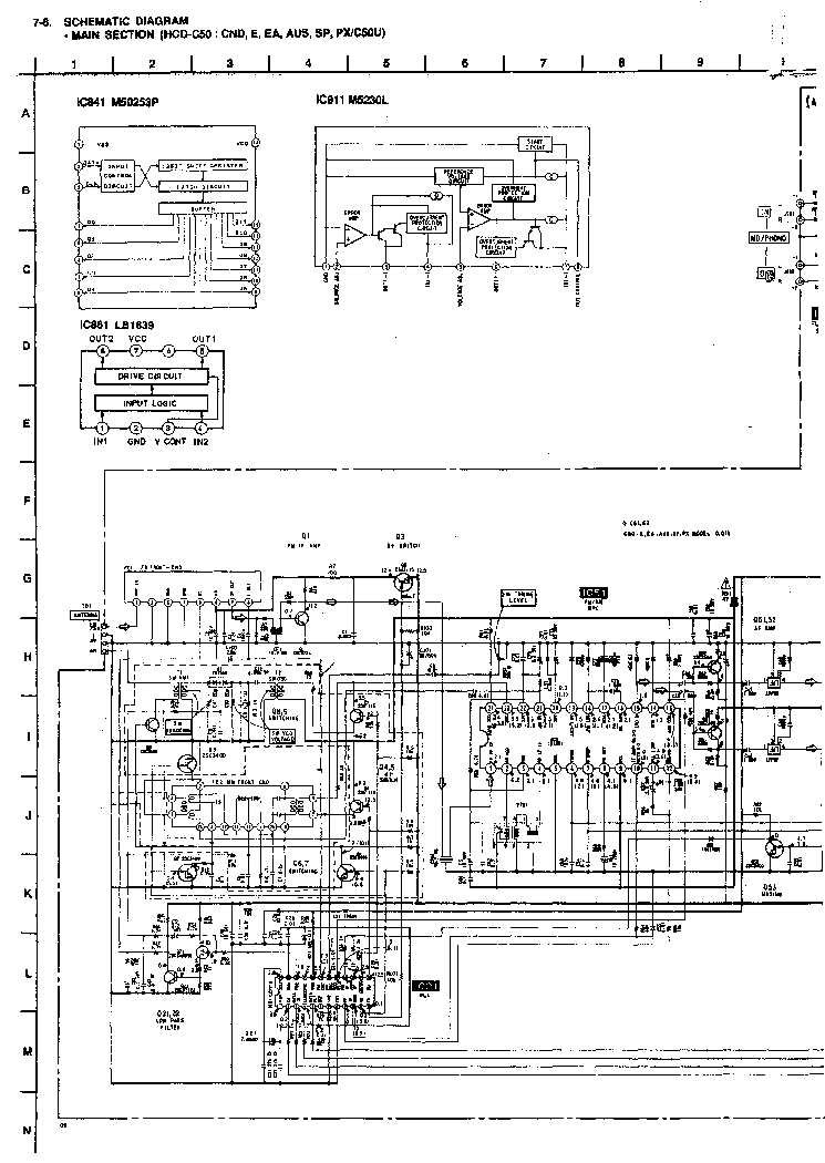
SONY CFM-313L

Type:  (PDF)
(PDF)
(PDF)Size
9.2 MB
9.2 MB
Page
17
17
Category
AUDIO
SERVICE MANUAL
AUDIO
SERVICE MANUAL
If you get stuck in repairing a defective appliance download this repair information for help. See below.
Good luck to the repair!
Please do not offer the downloaded file for sell only use it for personal usage!
Looking for similar sony manual?
Good luck to the repair!
Please do not offer the downloaded file for sell only use it for personal usage!
Looking for similar sony manual?
Advertisements

Document preview [2nd page]

Click on the link for free download!
Advertisements
Please tick the box below to get download link:
- Also known:
SONY CFM-313L CFM313L CFM 313 313L
- If you have any question about repairing write your question to the Message board. For this no need registration.
- If the site has helped you and you also want to help others, please Upload a manual, circuit diagram or eeprom that is not yet available on the site.
Have a nice Day! - See related repair forum topics below. May be help you to repair.
Warning!
If you are not familiar with electronics, do not attempt to repair!
You could suffer a fatal electrical shock! Instead, contact your nearest service center!
Note! To open downloaded files you need acrobat reader or similar pdf reader program. In addition,
some files are archived,If you are not familiar with electronics, do not attempt to repair!
You could suffer a fatal electrical shock! Instead, contact your nearest service center!
so you need WinZip or WinRar to open that files. Also some files are djvu so you need djvu viewer to open them.
These free programs can be found on this page: needed progs
If you use opera you have to disable opera turbo function to download file!
If you cannot download this file, try it with CHROME or FIREFOX browser.
Translate this page:
Relevant AUDIO forum topics:
Sziasztok. Adott egy Opel Vectra B 1998 évjáratú jármű ami multifunkciós volánnal rendelkezik (6 db. gomb, 3 oldalanként) és ebben az autóban a gyári magnó helyett egy Sony MEX-N5100BT van bekötve erősítővel meg nem gyári hangfalakkal stb... Tökéletesen működik a fejegység és mivel ő Steering Wheel ready, vagyis előkészített ilyen célra (Jack kijövetel), így csak egy jack kábel kellene nekem amit összehangolok a volánon lévő gombokkal. Ugye ellenállás elven működik a 6 db. gomb és a magnó képes értelmezni az értékeket lenyomáskor és egy adott funkciót hozzárendelni a gombhoz amit én szeretnék. Van rajzom a Sonyhoz, de nem tudok kiigazodni rajta sajnos :( Csatolom a rajzot amelyben a remote funkcíó J801-ként van jelölve és ha megnézitek a 30-ik oldalon a 3 csatlakozásból egyik föld a másik kettő pedig RC_IN0 és RC_IN1 viszont vannak ott valami pufferek és valami 1K Remote ami gondolom 1KOhm ellenállás akar lenni, vagyis az lehet a határ talán, de nem vagyok benne biztos, mivel nem vagyok jártas a témában. Egy másik rajzon is látható a remote funkció, ez a 36 oldalon található és szintén J801-ként van jelölve.
Na most a kocsi gombjaitól állítólag 2 vezeték jön az ISO csatiba, de még nem szedtem szét a volánt, szóval csak amit a neten találtam az alapján írom... Ha a 2 vezetéket ami jön a volántól bekötöm egy Jackivel a magnóba, akkor számít hogy melyiket hova? In_1 vagy IN_0 ? Tönkre tehetem-e a magnót ha nem kötöm be helyesen, vagy csak egyszerűen nem fog működni?
Elnézést ha picit pontatlan voltam helyenként, de ha bármi kérdés van állok a rendelkezésetekre. Előre is köszönöm a segítséget :) Szép estét, Csaba.
UI: Elnézést, nem tudom csatolni mert 6 Mb :( A rajz erről a linkről tölthető le.
Want to share:
Have downloaded the schematics from this forum to help repair the amplifier of a friend.
Turned out that Sony decided to route the earth through the chassis, even the earth between the various supplies.
When one takes the main board out of the chassis and switches the amp on, there are up to 20 volts difference between the eart (and hence reference) of the pre-amps and the main amps.
Luckily the amp goes into protection but from a design point of view it is not nice to rely on screws and aluminum face plates to conduct up to 0.2 amps of current from one supply to another.
What I did is solder wires to every eart point and connected them on the main board to make it stand alone and not rely on conducting current through the chassis anymore.
Bad design, simple repair but took some digging in the schematics to find out what exactly was going on!
Sziasztok!
Az erősítőbe felcseréltem a végfokokat, a hiba átment a másik oldalra. A hibridet kibontottam, mikroszkóp és röntgen alatt sem látszik rajta semmi. Gondolom valamelyik félvezető.
Van valakinek egy ilyen modulja a fiók mélyén? Esetleg valami +/-40V-os tápfeszültségű végfokmodul, amit be lehetne tenni?
Üdv. Jácint
Üdv!
Tudnátok segíteni?
Lenne egy ilyen ketyere.
Annyit csinál, hogy ütemesen flakkerol a főrelé, akkor is ha lehúzom a nagy trafót.
A kis stby trafó jó.
Mikor kéne húznia a főrelének?
https://elektrotanya.com/sony_str-gx215_gx315_gx415.pdf/download.html
Kösz
p.s.
Nézem a rajzot, vagy nem áll fel a B+ 5V, valamiért.......vagy a proci nem adja ki a power RY jelet.......
Similar manuals:
If you want to join us and get repairing help please sign in or sign up by completing a simple electrical test
or write your question to the Message board without registration.
You can write in English language into the forum (not only in Hungarian)!
or write your question to the Message board without registration.
You can write in English language into the forum (not only in Hungarian)!
E-Waste Reduce