
Dear Elektro Tanya members,
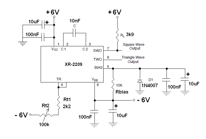
I am experimenting with a triangular wave oscillator built using the XR2209.
The waveform I get is distorted. The distortion increases with frequency and is noticeable from 2,000 Hertz.
At the points of change of slope of the waveform are observed spikes and a kind of damped sine wave.
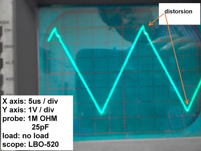
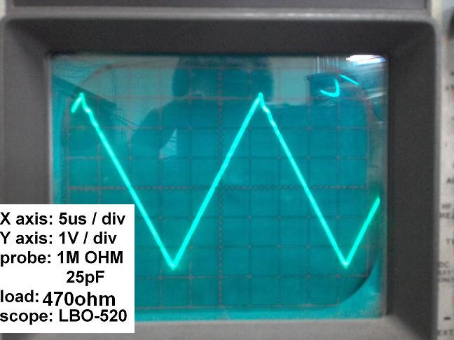
The waveform improves slightly loading the output with 470 OHM. The wave gets worse if a 10nF capacitor is placed in the output.
I want to know if anyone else has used the XR2209 and if you have any idea why this happens.
Thanks in advance!
Tisztelt Kollégák,
kérem egy nálam jobb angolos fordítsa le:
Lehet akár mérési hiba is, a tápegység legyen védőföld független, a 10MOhmos mérőzsinór
földelőcsipeszét a panel földjére kell tenni, és máshol ne is legyen összeföldelve a műszer a panellel.
üdv
bbgames
0
szia: remélhetőleg nem kapcsolótápról üzemel
Bálint
0
The waveform looks a bit better without resistor in square wave output.
I think my board design is bad.
Thanks Feri , Kari, Edmundson and bbgames!
0
Hi!
Try to replace the D1 to the faster 1N4148. The recommended capacitor on the bias line is 1uF. Replace the 10uF to 1uF. The triangle output has 10 Ohm impedance. Do not load with 470 Ohm. Add a voltage follower opamp at the output.
BR.
0
Thanks Edmunson for your interest!!
The capacitors are for decoupling, and diode D1 for biasing. In fact I have shorted D1 and only a DC of 0,6V have changed in the wave. Spikes remain.
I try to use a unity gain follower and problem remains. Then, i have put a simple RC filter and waveform is better.
But i am not happy with this solution, i think that the signal output of the XR2209 must be clean.
Maybe my chip is faulty. I will try another.
BR.
0
Hi,
You are right, this is not good solution. Do you use the square wave signal? If not remove the pull-up resistor RL. The fast rise and fall edges may be added to the triangle signal. In addition "To avoid parasitic pick up, timing resistor leads should be kept as short as possible." For the timing resistor is recommended to use metal film SMD.
The timing capacitor should be a foil type. Do not use SMD or multi layer capacitor.
To be honest, I used this IC for a long time but I do not remember a phenomenon like this. I had temperature issues because I used SMD for timing cap.
BR
0
HI,
"had temperature issues because I used SMD for timing cap."
What about SMD as COG/NPO? :-)
Kari
0
Hi Kari!
I haven't got real experience with COG/NPO. But all ceramic caps are sensitive to the mechanical vibration due to the piezoelectric effect. So it calls microfonia. Therefore is not a good choice for the timing cap. Just try to hit your DSO's top or its BNC signal input with a wood or plastic stick and see what happens. :) That caused by a huge numbers of SMD multi-layer caps used in it.
David L. Jones made a instructive video on its blog: https://www.youtube.com/watch?v=WE9pYUVvr00
BR.
0
Hali BR!
Interesting, but their are clearly depending of equipments and PCBs construction, or even from type and value of discussed capacitor!
Coupling Cs have usully (in higher values/over 10nF only) X7R, or more bad-Y5u and so, dielectricum and as Dave sad too; have very thin layers of ceramics(more sensitive agains mechanical stresse), but an (yet at 5nF) COG hase more massive size/thicker material layers, also must have less parasitic effects...
Its good to checkout-for experimenting_I belive.
BTW; you can buy over much decads "less microphony" coaxial cables, in example, for piezo (accelerating) sensors :-)
Kari
0
https://www.promelec.ru/pdf/xr-2209.pdf
see page 11 (bias -> gnd)
regards
bbgames
0
Hi!: Is the ringing visible at lower frequency (for example at 0.5 or 1kHz)? It's possible that the PCB (maybe grounding) design, wrong.
With Best Regards: Feri
0