
After trying alot of things to fix a drift issue which helped but did not quite cure the issue I decided to rebuild the lvps section of the AF-AVR board and also incorporate
a modification that is out there on the web shown here :
[ https://www.radiomods.co.nz/kenwood/kenwoodts830.html ]
After changing the zener, and putting in new resistors from C-E I didnt have any 9V output from the board anymore when put back into the chassis.
I removed it and tested on my bench with a 16.5VDC input to L5 and it seems to more or less work when I apply a load to the 9V line, however when I vary
VR4 the 9v level does not vary. I had seen that vary and adjust the 9v output back before I began the work, so I know the pot works.
At one point I had the test voltage applied backwards during my bench tests, but I dont think I left it on long enough to do harm, as there was no smoke coming from anything.
When it was first installed into the chassis, and dre current I did smell a resistor burning so I had shut it down. The smell seemed to come from near where the 9v is generated,
but cant see anything obviously burned. Attached is a pix of the lvps and theres a llink to the entire schematic of the radio.
[ http://www.mediafire.com/file/o9ajn6g3p0gi19m/schematic.pdf/file ]
I did notice I have 49 ohms to gnd when the board is installed from the post marked (12) which is the collector of Q34. Thats kind of a low reading
and I see it runs back to the main power supply board to a relay but I dont understand what that relay is doing. The 12V also seems to go to the PLL
board and one other location, but 49 ohms seems strange, unless there is a short on the transistor now after putting the mica insulator on the new transistor.
Any feedback or comments appreciated on how to confirm the issue appreciated.
Hi!
Have You change, among others the value of zener (D25) from 6V1 to 5V3?
Feri
1
Yes its a 1N4733. D26 was changed first as a test because something seemed cold spray sensitive in that area, its a 9V zener but when I replaced it, there was no help.
That was before I decided to rebuild everything in those circuits and install the C-E resistors on the power transistors. The original power transistors were 2SA473's hard to find so
my parts vendor said to sub 2SB707 so I used those. I suppose they could be bad from supplier but never had bad semis from this source. I hear from others that we are now in the day that
all parts we get as NEW should be tested and not assumed anymore to be good.
0
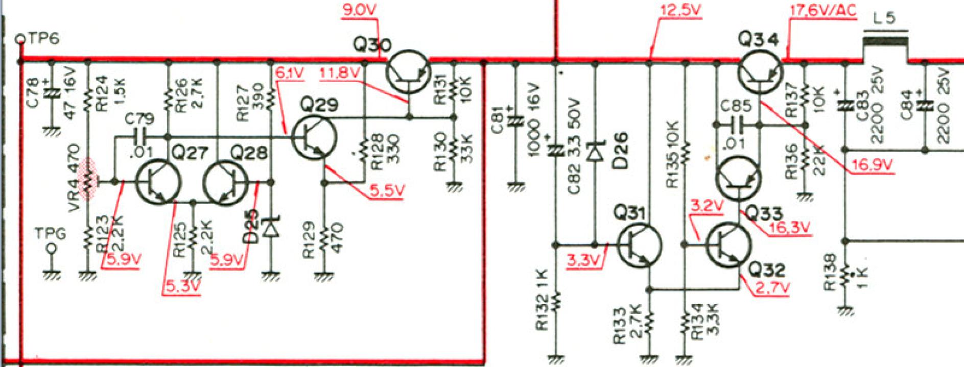
Ok, I have something: VR4 provide output regulation of 8-10V but what is
intresting, that the supply work correctly only when it is properly loaded.
For example, this means that the 9V output load must be at least equivalent
to 300R. If not, it retains around 9V (still unregulated), but 12V side value
can rise up to input voltage (17.5V - raw).
Both side 12V and 9V must be properly loaded (they should not hang).
.........................
Similar problem occurs when it is overloaded. Circuits have no overcurrent
sensor but even than, if the load is high on 9V side (right below 35R) it is
drop suddenly below 2V. At same time 12V side can rises his value up to 16V.
This phenomenon can be explained by the insufficient amplification
property of a transistor (Q34)
1
Hi -
Yes interesting. Were you using the upgraded diode and resistors in the 9v circuit? They claim regulation was greatly improved with those changes and the 22k ohm resistors.
Also what were you using for Q30 / 34?
0
Hi. The attached circuit was used, without 22k connected over C-E.
In simulation, Q30 and Q34 are with value of Beta slightly higher then 100.
1
Hi - I guess my Q30/34 could have poor beta. Would regulation be more stable with load resistors on the 12 and 9 v outputs, then ran to power the radio? I know during normal operation
the heat sink heats up fairly good, but it takes a long time sand during that time period is the voltage drift which is reflected into the vfo output frequency. Perhaps loading it much more
means temperature comes up higher, and stabilizes faster?
0
Hi
The temperature dependency test for each part is time consuming but
the previously attached circuit have some solution for this issue.
I sugest to use trasistors with relativelly high beta associated with high curent capability.
Maybe only Japanese transistors can handle this?
1