Service manuals, schematics, eproms for electrical technicians
RCA RF SIGNAL GENERATOR 1955 SCH

Type:  (JPG)
(JPG)
(JPG)Size
154.0 KB
154.0 KB
Page
---
---
Category
METER
SERVICE MANUAL
METER
SERVICE MANUAL
If you get stuck in repairing a defective appliance download this repair information for help. See below.
Good luck to the repair!
Please do not offer the downloaded file for sell only use it for personal usage!
Looking for similar rca manual?
Good luck to the repair!
Please do not offer the downloaded file for sell only use it for personal usage!
Looking for similar rca manual?
Document preview [1st page]

No preview item for this file.
Possible causes:
- No preview picture generated yet.
- It is not a pdf file.
Advertisements
Download free of charge (10 files / day):

Download processing...
Download processing...
- Also known:
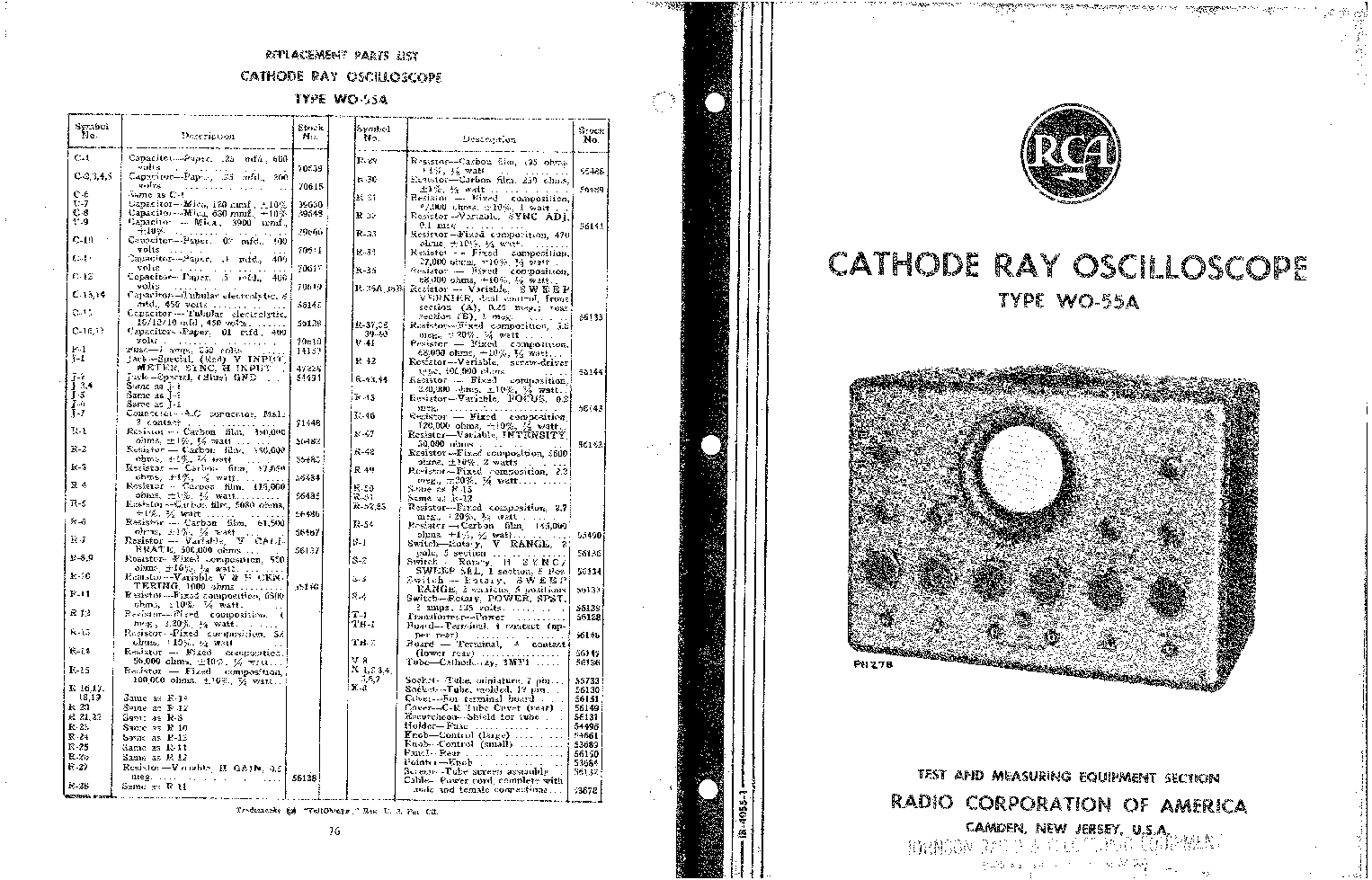
RCA RF SIGNAL GENERATOR 1955
- If you have any question about repairing write your question to the Message board. For this no need registration.
- If the site has helped you and you also want to help others, please Upload a manual, circuit diagram or eeprom that is not yet available on the site.
Have a nice Day! - See related repair forum topics below. May be help you to repair.
Warning!
If you are not familiar with electronics, do not attempt to repair!
You could suffer a fatal electrical shock! Instead, contact your nearest service center!
Note! To open downloaded files you need acrobat reader or similar pdf reader program. In addition,
some files are archived,If you are not familiar with electronics, do not attempt to repair!
You could suffer a fatal electrical shock! Instead, contact your nearest service center!
so you need WinZip or WinRar to open that files. Also some files are djvu so you need djvu viewer to open them.
These free programs can be found on this page: needed progs
If you use opera you have to disable opera turbo function to download file!
If you cannot download this file, try it with CHROME or FIREFOX browser.
Translate this page:
Relevant METER forum topics:
Hozzájutottam egy Hitachi V-212-es oszcilloszkóphoz.
Egy-két hiba zavar a működésbe.Azt szeretném megtudni, hogy egyszerűen javítható
vagy nem érdemes foglalkozni a hibákkal ?
- alapállapotban a vízszintes jel hullámzik, lebeg ( és ez befolyással van a méréseknél is )
- A saját kalibráló jele csak olyan 250mV körüli és a fűrész jel függőleges élei szinte nem is látható
( hiába állítom az intensivity-t max.-ra )
- Úgy emlékszem, hogy a szkópoknál megállítható a jel felrajzolása, hogy egy álló képet kapjak, de itt hiába állítom az
időalapot és a swap-ot, nem sikerül állóvá tenni.
Gondolom a tápját át kellene nézni,de mielőtt szétszedném érdekelne, hogy lehet-e ezeket a hibákat orvosolni ?
Üdv a csapatnak!
Néhány órája kaptam ezt a szerkentyűt.
Gond: nem műxik a fókusz.
Mindkét ch. megy. Jobban még nem tudtam elmélyedni benne, m.madzag nincs hozzá...
Kérdésem, hogy a gond megoldása után kb. mennyit érhet jó ungarische forintokban?
Egyébként sérülésmentes, jól néz ki.
kösz.
ET-n van e esetleg ki címben említett műszereket gyűjt és javít?
Tapasztalatok és alkatrész helyettesítések ,esetleg érdekes régi olyan műszerrel rendelkezik mit az Orion gyártott az EMG megalakulása előtt! Szeretném főleg ezekről ha van rá mód képet tennének fel esetleg ha kapcsolási rajz is elérhető még jobb lenne!
Esetleg ha keres valaki valamit (poti,cső,kondi stb ) itt meg beszélhető lenne! (Tudom ez nem az a fórum ahol adok-veszek van)!!! Nem is ez lenne a lényeg!
Vannak speciális EMG alkatrész gyártmányok amik sehol nem elérhetőek!
Köszönöm hogy el olvastátok !
Egy kicsibe nyomuló EMG műszer gyűjtő tollából az írás!
Tisztelettel mindenkinek
Zoli
Some months ago I bought a Marconi TF 2008, I knew that the instrument not was fully functional. When I started faultfinding I realized that the wiring was wery complex. By help of schematics that can be downloaded from many sites I started to sort out the wiring between all the modules in A30. It took quite a while but was to great help when I started the faultfinding. First of all I replaced all electrolytic capacitors, found several capacitors that were broken. The main problem was that the Carrier range positions 2, 6, 8 and 10 did not work. The problem for range 2 was an broken inductor L1, in module A8. The fault for range 6,8 and 10 was a broken connection between R4:s center pin and R3 in module A23 (bad soldering). To help anyone with faultfinding I share my ownmade drawings in the attached PDF.
Similar manuals:


If you want to join us and get repairing help please sign in or sign up by completing a simple electrical test
or write your question to the Message board without registration.
You can write in English language into the forum (not only in Hungarian)!
or write your question to the Message board without registration.
You can write in English language into the forum (not only in Hungarian)!
E-Waste Reduce