Service manuals, schematics, eproms for electrical technicians
C 9 7 USSR OSCILLOSCOP

Type:  (ZIP)
(ZIP)
(ZIP)Size
11.5 MB
11.5 MB
Page
---
---
Category
METER
SERVICE MANUAL
METER
SERVICE MANUAL
If you get stuck in repairing a defective appliance download this repair information for help. See below.
Good luck to the repair!
Please do not offer the downloaded file for sell only use it for personal usage!
Looking for similar c manual?
Good luck to the repair!
Please do not offer the downloaded file for sell only use it for personal usage!
Looking for similar c manual?
Document preview [1st page]

No preview item for this file.
Possible causes:
- No preview picture generated yet.
- It is not a pdf file.
Advertisements
Download free of charge (10 files / day):

Download processing...
Download processing...
- Also known:
USSR
- If you have any question about repairing write your question to the Message board. For this no need registration.
- If the site has helped you and you also want to help others, please Upload a manual, circuit diagram or eeprom that is not yet available on the site.
Have a nice Day! - See related repair forum topics below. May be help you to repair.
Warning!
If you are not familiar with electronics, do not attempt to repair!
You could suffer a fatal electrical shock! Instead, contact your nearest service center!
Note! To open downloaded files you need acrobat reader or similar pdf reader program. In addition,
some files are archived,If you are not familiar with electronics, do not attempt to repair!
You could suffer a fatal electrical shock! Instead, contact your nearest service center!
so you need WinZip or WinRar to open that files. Also some files are djvu so you need djvu viewer to open them.
These free programs can be found on this page: needed progs
If you use opera you have to disable opera turbo function to download file!
If you cannot download this file, try it with CHROME or FIREFOX browser.
Translate this page:
Relevant METER forum topics:
Üdvözlet,
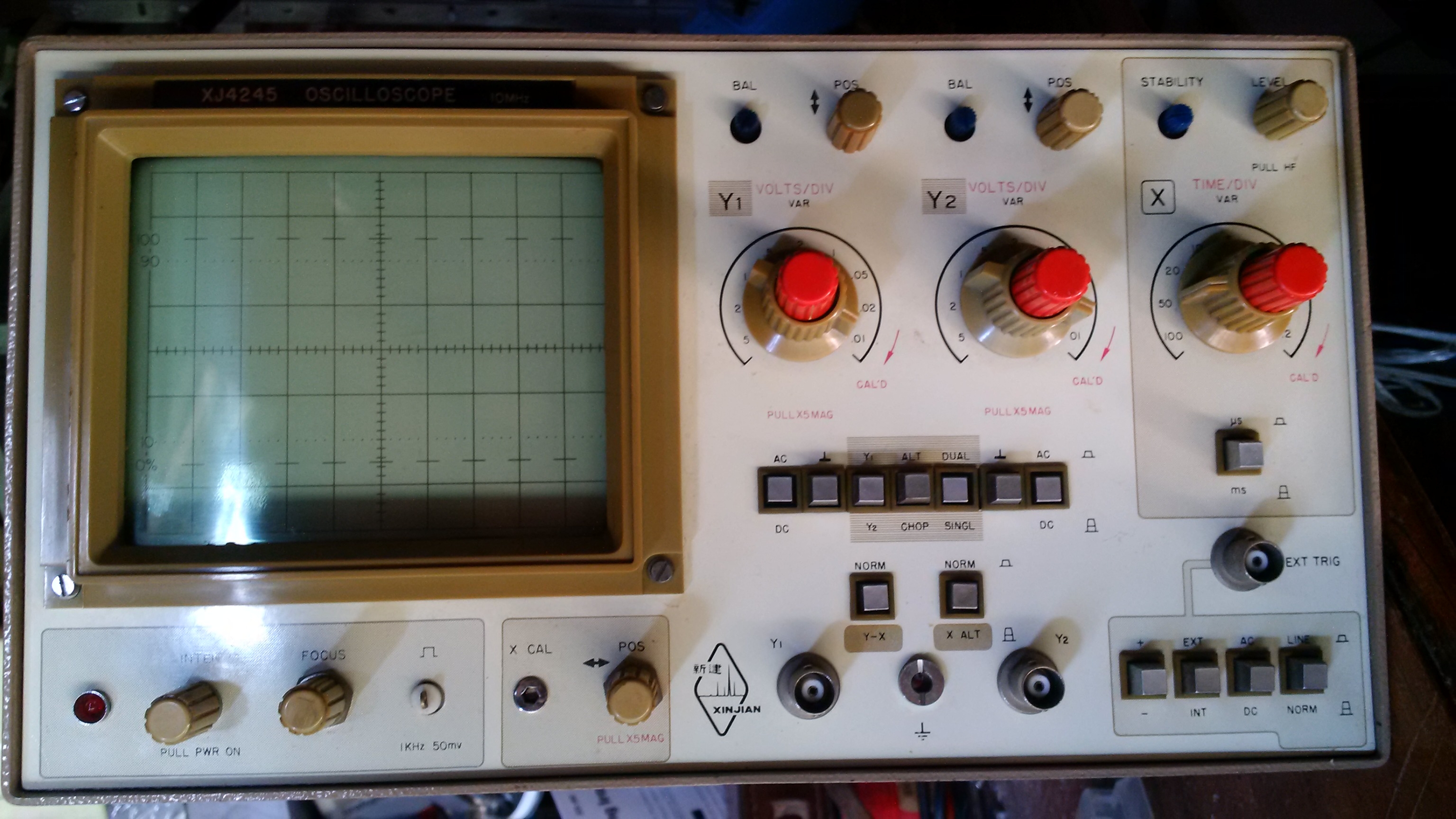
a napokban szereztem be a címben említett kínai csodát. A '90-es évek elejéről származhat. Gyártója a XinJian vállalat, róluk csak annyit találtam, hogy még az elektroncsöves korszakban is mérőműszereket gyártottak.
Az oszcilloszkóp, az eladó szerint, postázás előtt működőképes volt, hozzám már így ért.
Megkímélt állapotban van
Bekapcsoláskor a 2KV-os táp működése csak 3-4" hallható, ezután elkezd akadozni, majd elhallgat, és azzal egy időben pár másodpercig halkan perceg (áthúz), majd abbahagyja. Azonnali újraindításkor ez nem jelentkezik, de ha hagyom pihenni egy pár órát, akkor igen:
https://www.youtube.com/watch?v=timil1lJEaE&feature=youtu.be
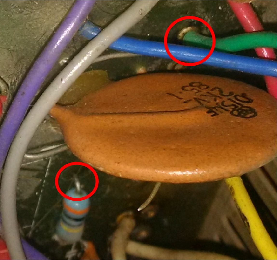
A megjelölt helyeken húz át, szak az alkatrész felőli oldalon, körkörösen a lábak körül. A fenti (zöld vezeték) a katódcső 4. lábéra vezet és elméletileg -2KV kéne legyen rajta, az ellenállás a fókuszállító potenciométerhez van kötve. Ezt látva kikötöttem a csövet, de nélküle is ugyanúgy viselkedik.
A cső tápja a +/-2KV helyett csak 1.3KV-to ad.
A nyákon találtam 3-4 feltüntetett feszültségértéket, amik rendben vannak, leellenőriztem az 1KHz/50mV-os négyszögjelet ez is rendben van.
Az áthúzásnál az az érdekes, hogy egyik sem irányzottan húz át, hanem inkább körkörösen kisülnek, az ellenállás közelében semmi nincs, a zöld vezeték ugyanúgy viselkedik, még a vele összekötött varisztor irányába is.
Az áthúzások környékét lepucoltam, de nem segített.
Ötleteket/tanácsokat előre is köszönöm.
Csaba
a napokban szereztem be a címben említett kínai csodát. A '90-es évek elejéről származhat. Gyártója a XinJian vállalat, róluk csak annyit találtam, hogy még az elektroncsöves korszakban is mérőműszereket gyártottak.
Az oszcilloszkóp, az eladó szerint, postázás előtt működőképes volt, hozzám már így ért.
Megkímélt állapotban van
Bekapcsoláskor a 2KV-os táp működése csak 3-4" hallható, ezután elkezd akadozni, majd elhallgat, és azzal egy időben pár másodpercig halkan perceg (áthúz), majd abbahagyja. Azonnali újraindításkor ez nem jelentkezik, de ha hagyom pihenni egy pár órát, akkor igen:
https://www.youtube.com/watch?v=timil1lJEaE&feature=youtu.be
A megjelölt helyeken húz át, szak az alkatrész felőli oldalon, körkörösen a lábak körül. A fenti (zöld vezeték) a katódcső 4. lábéra vezet és elméletileg -2KV kéne legyen rajta, az ellenállás a fókuszállító potenciométerhez van kötve. Ezt látva kikötöttem a csövet, de nélküle is ugyanúgy viselkedik.
A cső tápja a +/-2KV helyett csak 1.3KV-to ad.
A nyákon találtam 3-4 feltüntetett feszültségértéket, amik rendben vannak, leellenőriztem az 1KHz/50mV-os négyszögjelet ez is rendben van.
Az áthúzásnál az az érdekes, hogy egyik sem irányzottan húz át, hanem inkább körkörösen kisülnek, az ellenállás közelében semmi nincs, a zöld vezeték ugyanúgy viselkedik, még a vele összekötött varisztor irányába is.
Az áthúzások környékét lepucoltam, de nem segített.
Ötleteket/tanácsokat előre is köszönöm.
Csaba
Sziasztok!
A címben olvasható hiba miatt a műszer nem használható, de szeretném a segítségetekkel újra használható állapotba hozni.
Hol keressem a hibát?
Köszi a segítséget!
A címben olvasható hiba miatt a műszer nem használható, de szeretném a segítségetekkel újra használható állapotba hozni.
Hol keressem a hibát?
Köszi a segítséget!
Kedves Mindenki!
Szeretném kérdezni, hogy van-e valaki, aki ismeri a nevezett műszert? Sajna semmi infót nem találok róla.
Köszi!
Szeretném kérdezni, hogy van-e valaki, aki ismeri a nevezett műszert? Sajna semmi infót nem találok róla.
Köszi!
Szerbusztok!
A KS cső nem alkalmas 15 mega fölötti használatra...
Sikerült szert tennem egy RFT EO213 oszcilloszkópra. Kivakartam a koszból és megjavítottam.
Azonban a forgókapcsolói a belefújt majd fél tubusnyi Tuner600 ellenére kontakt hibásak. Sajnos szét kell szerelnem és az érintkezőket le kell sikálnom.. Álom meló.
De, ha már úgyis ki kell építeni és szanaszét fogom szedni, akkor talán érdemes lenne valamit tenni a 10 Mhz sávszélesség kitologatására. A neten annyit sikerült találnom, hogy a feteket érdemes cserélni és máris jobb.
Nos hát most felteszem itt is a kérdést! A nálam okosabb, tapasztaltabb kollégák mit mondanak, mit tegyek a cél érdekében?
Köszönöm!
http://www.radiomuseum.org/r/conrad_voltcraft_oszilloskop_202.html
Similar manuals:


If you want to join us and get repairing help please sign in or sign up by completing a simple electrical test
or write your question to the Message board without registration.
You can write in English language into the forum (not only in Hungarian)!
or write your question to the Message board without registration.
You can write in English language into the forum (not only in Hungarian)!
E-Waste Reduce