
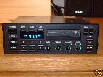
Pix of Radio here - [ http://www.amstereo.org/ford-st.jpg ]
Found some diagrams online and posted them here:
http://www.mediafire.com/folder/kfg508n7eah2y/FORD
Do I need to jumper any pins on the connector to gnd or B+ to get proper power into the radio?
Steve Hearns
Technotronic Dimensions [USA]
WWW.TECHNOTRONIC-DIMENSIONS.COM
hi
0
Hi Steve,
I think, connection you made is correct. Because this radio is fairly old and uncommon in EU I can try to help you, based on my experience. So I think, after you changed bad caps, the problem is with backup cap, about 0.5F. This cap can produce very uncommon errors like this. Some picture(s) from inside of radio would be nice if attached to post.
best reards
bakó zoltán
blue moon service
ps
sorry about my english
1
Hello -
Added 2 new photos to that shared folder "FORD".
http://www.mediafire.com/folder/kfg508n7eah2y/FORD
One is the small board with caps on it that folds open with a cable. The one I am working on, the cables eventually started
cold-working and broke, so I clipped and unsoldered both of them and used a 26 gauge ribbon cable from a TV power supply in its place. I thought this cable was the cause of
the problems, but the same problems are still there.
The other photo is the main board. The gren caps are Nichicon brand and are the originals Im told go bad and should be all replaced on both boards.
There are 2 or 3 larger caps toward the left side which on the one I am working on, I did not bother replacing as they looked good. The photos I put up just now are from
another radio same model I got in for repair. Its my hopes by studying one versus the other, I can make progress getting them both working, as they reportedly had different
symptoms relating to the bad caps. I already found 1 burned SMD resistor on the other, and was able to determine its 10 ohms , not 33 which the radio I have not worked on is reading
for value.
I'd have to open up the radio that I have repaired and am testing some more to get good photos, and will do that later. One thing I notice is both radios have the same model number and
nearly 100% component populations, save for the newer one which is missing some 68uF caps that were in the other.
I think you may refer to the supercap component which holds memory etc? I'm not sure if its one of the caps I didnt replace, those larger ones but will check. The new radio I have not worked on has signs of those larger caps leaking very badly. I cleaned the corrosion off , but have not yet powered the radio to confirm the problem. The other caps in that radio look
to be still in very good shape, with no signs of leakage, but to do these right, I'm told means entire recapping.
There was a youtube video on these model radios in I think Polish, but either it was removed or I'm not allowed to see any feeds from that part of the world anymore....
0
Ok, took photos of the radio I had repaired. Mainboard, the daughter board and the removed tape mechanism:
http://www.mediafire.com/folder/8kg58w3pv8bwg/FORD-REPAIRED
Theres 2 caps on the mainboard picture on the left, one is larger and a smaller one is standing up next to it, they are:
C001 : 2700uF / 16v
C003 390uF / 16v
I didnt bother changing these as I was told the nichicon low profile ones go bad, but I removed and checked them and they are in quite good shape.
I dont see signs of corroded feed-thrus near the caps I changed. I felt my work quality was good, so was surprised this is not working.
One thing I did notice is on the repaired radio, some caps I didnt replace are square plastic light tan color, and on the other radio
they are using low profile electrolytic types for them. There are also some tantlum caps on the main board near the left side, but
its so rare I replace a tantlum, I didnt think it worth checking them.
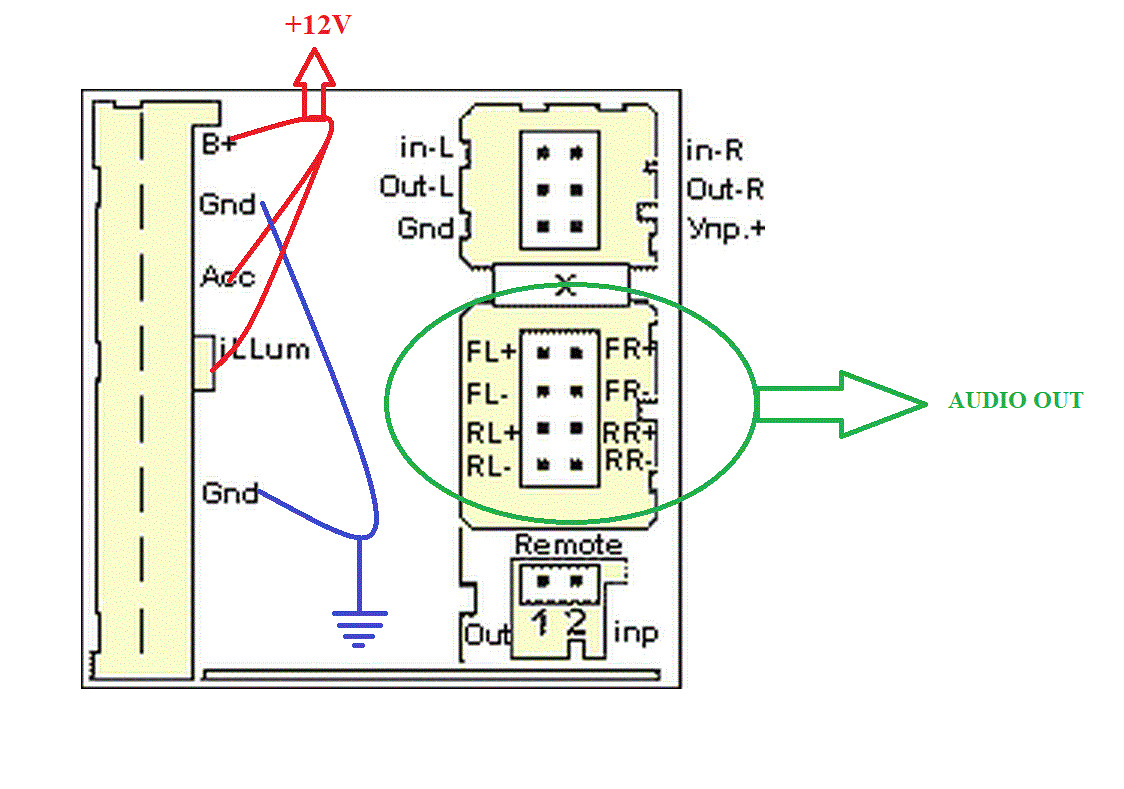
Another tech in one of my groups says the pin labeled "Bat" is 12V all the time and the "ACC" is switched from the ignition also 12V.
So I think I am only applying power to the 12V pin, and not the ACC and its showing some parts of the display lighting up. It seems to me maybe
proper operation means 12V on the batt is for the clock and memory and usually it would mean the clock comes on when you turn the igniton, but
this is a 1988 design so there may not be a clock.
0
UPDATE -
On the recapped radio, I jumpered Bat (pin 1) to Acc (pin 3) , and monitored current from a 1A
12V supply. Drew about 138mA, the display flashes all the segments if I remove and re-apply the power with
the alligator clips.
Pressed the power button several times, nothing.
I went and fed the illum pin (#4) 12V too, no difference, no additional
current drawn.
I unplugged the tape deck to see if theres an issue there, and no
difference.
All thats left is grounding pin #2?
I am grounding the power right now to the chassis of the radio, which is the
same as pin #6, so Im leaving that alone.
Pin 1 is drawing the 138mA, and it seems to be lighting the Dolby buttons
backlight bulb, so that current seems about right for 1 small bulb, but behind the faceplate
theres more bulbs mounted than that one that dont appear to be lighting.
Theres also a board mounted to it and has what looks like a DC-DC converter
module mounted on it, but have not removed it yet for inspection. Its got some caps mounted on it,
and they dont seem to show any signs of leakage from what I can tell.
I'm thinking maybe theres issues with that board.
I may swap in the faceplate from the other radio as a test, but I want to make sure
I'm applying power correctly and not burn anything out.
So far I have not "let the smoke" out of anything, so maybe Im not too bad off......
0
Hello!
I am writing via Google translator so my English is very bad.
power wires.
Very bad flat paper cables.
Continuing the theme of this radio - Bluetooth installation
https://youtu.be/jG3Z3dYifOI
.
1
Ooo, thanks, thats great drawing !
Yes, the cable on small pcb inside on mine broke, so I transplanted a used cable from junked out TV in my shop. After I replaced all the electrolytic caps,
I tried power, and the display segments were only partially lighting up, so I set aside on bench, now a year later I am trying again.
There was some corriosion on the component side near some caps, as the electrolyte damaged the traces, but I did not see any breaks. So I merely
remove corrosion with old toothbrush, and clear coat with nail polish for protection.
I will post next results here, thanks for your videos.
0
Ok I was able to power the item up using the diagram you supplied.
There is a tape already inside, so the display says "tape". At least the display seems to be working better now.
But when you press eject, the door does not open, and it tries to force it through the door, so I guess when I re-assemble
the faceplate, I didnt flip the door up so its on the hinge that opens it.
0