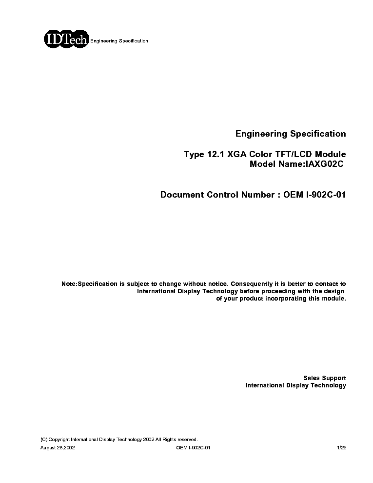
IDTECH IAXG02 LCDPANEL DATASHEET

155.7 KB
26
DATASHEET
OTHER
Good luck to the repair!
Please do not offer the downloaded file for sell only use it for personal usage!
Looking for similar idtech manual?

Download processing...
- Also known:
IDTECH IAXG-02 DATASHEET IAXG02 LCDPANEL IAXG 02
- If you have any question about repairing write your question to the Message board. For this no need registration.
- If the site has helped you and you also want to help others, please Upload a manual, circuit diagram or eeprom that is not yet available on the site.
Have a nice Day! - See related repair forum topics below. May be help you to repair.
If you are not familiar with electronics, do not attempt to repair!
You could suffer a fatal electrical shock! Instead, contact your nearest service center!
so you need WinZip or WinRar to open that files. Also some files are djvu so you need djvu viewer to open them.
These free programs can be found on this page: needed progs
If you use opera you have to disable opera turbo function to download file!
If you cannot download this file, try it with CHROME or FIREFOX browser.
Touch sensors have transformed how humans interact with electronics. From smartphones and home automation panels to industrial machines, these components make control effortless and intuitive. The next generation of touch sensor technology takes this even further — delivering faster response times, higher sensitivity, and greater reliability.
Understanding Capacitive Touch SensorsCapacitive touch sensors detect and respond to touch input by measuring variations in capacitance. When a finger approaches the sensor surface, the body’s natural electric field disturbs the sensor’s electrostatic field, resulting in a measurable change.
Unlike resistive touch sensors that require pressure, capacitive sensors operate through proximity and charge displacement. This makes them more durable and suitable for applications requiring frequent use and smooth surfaces, such as modern touchscreens or sleek control interfaces.
Working PrincipleA typical capacitive touch sensor consists of an electrode, an insulating layer, and a substrate. When a conductive object (such as a human finger) nears the electrode, it alters the local capacitance. The sensor circuit detects this small change and triggers a signal output.
This principle allows touch sensors to respond instantly, even without physical movement of parts. In most modules, three basic pins are used:
-
VCC for power supply
-
GND for ground reference
-
OUT (or SIG) for the signal output that indicates a touch event
These simple connections make integration with microcontrollers and embedded systems straightforward.
Advantages of Next-Generation Touch SensorsModern capacitive touch sensors offer several advantages over older mechanical or resistive types:
-
High Sensitivity – They detect even very light touches with minimal delay.
-
Durability – No moving parts mean long operational life and consistent performance.
-
Fast Response – Electrical detection ensures rapid signal processing and response times.
-
Robust Operation – Advanced filtering techniques reduce false triggering from noise or interference.
-
Design Flexibility – Can be embedded behind glass, plastic, or acrylic for sleek, sealed surfaces.
These benefits make them ideal for compact, modern designs in consumer, industrial, and automotive electronics.
Common ApplicationsTouch sensors today appear across many fields:
-
Consumer Electronics – Smartphones, tablets, and portable devices.
-
Home Automation – Smart light switches, touch thermostats, and appliance controls.
-
Automotive Systems – Dashboard controls, infotainment systems, and steering wheel touch inputs.
-
Medical Equipment – User interfaces for diagnostic or monitoring instruments.
-
Industrial Control Panels – Reliable operation in environments where mechanical switches might wear out.
In each of these areas, touch sensors replace traditional buttons, improving both reliability and user experience.
Key Parameters and PerformanceTypical electrical and physical parameters for a touch sensor module include:
-
Operating Voltage: 2.0 V – 5.5 V
-
Response Time: 60 ms – 220 ms
-
Output Voltage Levels: High ≈ 0.8 × VCC, Low ≈ 0.3 × VCC
-
Module Size: Approximately 24 mm × 24 mm
These values can vary slightly depending on the manufacturer and the design of the electrode.
Design and Implementation Tips-
Proper Grounding and Shielding: Minimize electromagnetic interference to prevent false triggering.
-
PCB Layout Care: Keep electrode traces short and away from high-frequency or noisy lines.
-
Sensitivity Adjustment: Many modules allow tuning for optimal performance depending on surface material.
-
Software Debouncing: Filter out rapid transitions to ensure clean signal detection.
-
Environmental Considerations: Humidity, dust, and temperature changes can affect sensitivity — testing in real conditions is crucial.
Following these principles ensures consistent and reliable sensor performance.
Practical ConsiderationsTouch sensors are designed for longevity. With proper storage in a dry, ventilated environment and protection against static discharge, they can remain functional for years. Additionally, designs can be customized in size, shape, and sensitivity to match specific application needs.
ConclusionNext-generation touch sensors represent a major step forward in interactive technology. Their precision, reliability, and design flexibility allow engineers to create user interfaces that are not only functional but also visually refined and durable.
Whether used in consumer products, industrial machinery, or medical systems, these sensors bridge the gap between humans and electronics — turning a simple touch into powerful control.
or write your question to the Message board without registration.
You can write in English language into the forum (not only in Hungarian)!

